
Instruction manual


7. COMMUNICATION DATA LIST
IMR01Y06-E6
68
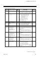
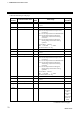
Continued from the previous page.
Extension
number
Communication item
Attri-
bute
Data range
Factory
set value
181
Timer 1
R/W
0.0 to 600.0 seconds
Customization tool is necessary when the
timer function is availed.
0.0
182
Timer 2
R/W 0.0
183
Timer 3
R/W 0.0
184
Timer 4
R/W 0.0
185 Unused
⎯ ⎯ ⎯
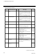
186
Energized/De-energized
R/W
Bit data
Bit 0: DO1
Bit 1: DO2
Bit 2: DO3 *
Bit 3: DO4 *
Bit 4 to Bit 15: Unused
Data 0: Energized
1: De-energized
[Decimal number: 0 to 15]
*
Unused on the FB100.
0
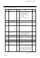
187
Alarm (ALM) lamp lighting
condition 1
a
R/W
Bit data
Bit 0: Event 1
Bit 1: Event 2
Bit 2: Event 3
Bit 3: Event 4
Bit 4 to Bit 15: Unused
Data 0: ALM lamp is not lit
1: ALM lamp is lit
[Decimal number: 0 to 15]
1111
(Bit image)
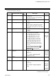
188
Alarm (ALM) lamp lighting
condition 2
a
R/W
Bit data
Bit 0: HBA1
Bit 1: HBA2
Bit 2 to Bit 15: Unused
Data 0: ALM lamp is not lit
1: ALM lamp is lit
[Decimal number: 0 to 3]
11
(Bit image)
189
Output status at STOP mode
R/W
Bit data
Bit 0: Event output and HBA output
Bit 1: Transmission output
Bit 2 to Bit 15: Unused
Data 0: OFF 1: Action continued
[Decimal number: 0 to 3]
0
a
When two or more items are set to “1: ALM lamp is lit,” if an error occurs in any one of these item, the alarm
lamp on the front of the controller (FB100/400/900) lights.
Continued on the next page.