
Instruction manual


4. WIRING
IMR01Y06-E6
14
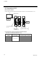
4.5 Installation of Termination Resistor
If communication errors occur frequently due to the operation environment or the communication
distance, connect termination resistors to the COM-JC and the controller. Procedure for setting a
termination resistor to Controller communication (RS-485) and its setting position are described in the
following.
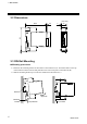
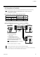
Termination resistor setting position
If the COM-JC is connected to the extreme end of the communication line, install one termination
resistor each to the COM-JC and the controller located most distantly from the COM-JC.
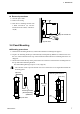
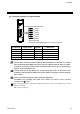
Setting procedure of termination resistor (COM-JC)
As the COM-JC is internally provided with a selector switch for choosing the ON/OFF of a
termination resistor, it is not required to externally install the termination resistor.
(Factory set value: Termination resistor connected)
1. Turn off the power supply of the COM-JC.
Do not separate the mainframe from terminal base with the power turned on. If so,
instrument failure may result.
2. Pull out the mainframe itself toward you while pushing the locks at its top and bottom (1), and
then separate it from the terminal base (2).
Upper-side
lock
Lower-side
lock
Top view
Bottom view
(2) Pull out
(1) Push
(1) Push
Terminal base
Mainframe
Removing the module mainframe
FB100
FB400
FB900
1
FB100
FB400
FB900
2
FB100
FB400
FB900
31
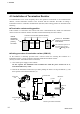
Controller communication (RS-485: Modbus)
COM-JC
Internal
termination
resistor ON
(Factory
set value
)
Connect a termination
resistor to the terminals
from exterior.
For installation position of
the termination resistor,
refer to Wiring (P. 13).