
Installation guide


GP-PRO/PBIII for Windows Ver. 6.1 PLC Connection Manual
Chapter 12 - Indicating Controllers
12-4-16
12.4 RKC INSTRUMENT INC. Controllers
12.4.3
Supported Devices
The following list shows the range of devices supported by the GP/GLC/LT.
CB Series / SR-Mini Series (Modbus protocol)
Enter the selected
Controller Slave
Address No.
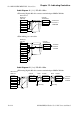
E.g. When entering Device Address 02EE
Enter the Device Name “...”, and the Word Address “02EE”.
01 ... 02EE
Device Name
Word Address
Controller’s Slave Address No.
01/02EE
Address
Controller’s
Slave Address No.
• GP/GLC/LT’s System Area (LS0 to LS19) Settings
The GP/GLC/LT’s system area (20 words) cannot be allocated to
the Controller’s own data area. When you are entering the sys-
tem area settings via the screen editor software or via the GP/
GLC/LT’s OFFLINE screen, be careful that you do not use the
Controller’s own data area.
• The data communication feature will not operate when the slave
address No. is set to “0”. ( The default value is 0.)
• Indicating Controller Slave Address settings can be entered in your screen
editor software. If a station number is not indicated, the previously en-
tered station number is automatically used. (The default value is 1.)
!!
!!
!
Important
Note:
Device Bit Address Word Address
Data 0000 ~ 02EEF 0000 ~ 02EE L/H
Comments