
Installation guide


GP-PRO/PBIII for Windows Ver. 6.1 PLC Connection Manual
Chapter 12 - Indicating Controllers
12-4-9
12.4 RKC INSTRUMENT INC. Controllers
Shield
Shield Shield
RDA
RDB
SDA
SDB
TERM
SG
FG
4 T(B)
5 T(A)
3 R(B)
2 R(A)
3 SG
6 Shield
COM.PORT1 COM.PORT2
COM.PORT1
COM.PORT2
COM.PORT2COM.PORT1
GP/GLC/LT
GP070-CN10-0
4 T(B)
5 T(A)
3 R(B)
2 R(A)
3 SG
6 Shield
4 T(B)
5 T(A)
3 R(B)
2 R(A)
3 SG
6 Shield
4 T(B)
5 T(A)
3 R(B)
2 R(A)
3 SG
6 Shield
4 T(B)
5 T(A)
3 R(B)
2 R(A)
3 SG
6 Shield
4 T(B)
5 T(A)
3 R(B)
2 R(A)
3 SG
6 Shield
Controller
No. 1
Controller
No. 2
Controller
No. n
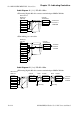
Cable Diagram 3 (1:1) RS-422 2-Wire
<When using Digital's RS-422 connector terminal adapter GP070-CN10-0>
<When making your own cable>
Shield
GP/GLC/LT
(25P)
Controller
Terminal
Block
SG
T/R(B)
T/R(A)
7 SG
9 TRMX
10 RDA
16 RDB
11 SDA
15 SDB
18 CSB
19 ERB
21 CSA
22 ERA
1 FG
Cable Diagram 4 (1:n) RS-422 4-Wire
<When using Digital's RS-422 connector terminal adapter GP070-CN10-0>
GP/GLC/LT
GP070-CN10-0
Shield
Controller
Terminal Block
RDA
RDB
SDA
SDB
TERM
SG
FG
T/R(B)
T/R(A)
SG
Resistance
120Ω
+
10%
or less
(Collective)
Resistance
120Ω
+
10%
or less
(Collective)