
Instruction manual


8 IMCB25-E3
6. OPERATIONS
6.1 Operation Procedures
1. Prior to starting operation, check that the mounting and wiring
have been finished, and that the SV and various parameters
have been set.
2. A power supply switch is not furnished with this instrument. It
is ready to operate as soon as the power is turned on.
(Factory set value: RUN).
This instrument holds the conditions that exist just before
the power is turned on. For example, if the power is turned
off in STOP mode, the instrument starts in STOP mode
when the power is turned on again.
RUN/STOP
Each time the <R/S key is pressed for 1 second, RUN/STOP
mode changes from RUN to STOP or STOP to RUN. If the
instrument is switched to STOP mode, its display, output, etc.
become as follows.
• Display: The PV display shows (STOP).
• Output: Control output OFF, Alarm output OFF
• Autotuning: AT canceled (The PID constants are not updated.)
RUN/STOP display (Z-1018 specification)
When operation is changed to the STOP mode by RUN/STOP
selection, a parameter symbol to indicate the STOP mode is
displayed on the SV display. Pressing the SET key with the STOP
mode displayed can also check and change the set value (SV).
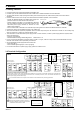
6.2 Set Data Lock (LCK) Function
The set data lock restricts parameter setting changes by key
operation. This function prevents the operator from making errors
during operation. There are 8 set data lock levels. (see below)
Set value Parameters which can be changed
0000 All parameters [Factory set value]
0001 SV, Alarms (ALM1, ALM2)
0010 All parameters except for Alarms (ALM1, ALM2)
0011 SV
0100 All parameters except for SV
0101 Alarms (ALM1, ALM2)
0110 All parameters except for SV and Alarms (ALM1, ALM2)
0111 No parameters (All Locked)
HBA, LBA and LBD can be locked when any of 0001, 0011, 0101 and
0111 is set.
Set Data Lock can be changed in both RUN and STOP
mode.
Parameters protected by Set Data Lock function are still
displayed for monitoring.
6.3 Autotuning (AT) Function
Autotuning (AT) automatically measures, calculates and sets the
optimum PID and LBA constants. The following conditions are
necessary to carry out autotuning and the conditions which will
cause the autotuning to stop.
Caution for using the Autotuning (AT)
When a temperature change (UP and/or Down) is 1°C or
less per minute during Autotuning, Autotuning may be
cancelled before calculating PID values. In that case,
adjust the PID values manually. It is possible to happen
when the set value is around the ambient temperature or
is close to the maximum temperature achieved by the
load.
Requirements for AT start
Start the autotuning when all following conditions are satisfied:
• Prior to starting the AT function, end all the parameter settings
other than PID and LBA.
• Confirm the LCK function has not been engaged.
When the autotuning is finished, the controller will
automatically returns to PID control.
Requirements for AT cancellation
The autotuning is canceled if any of the following conditions exist.
• When the set value (SV) is changed.
• When the PV bias value is changed.
• When the RUN/STOP mode is changed to the STOP mode.
• When the PV becomes abnormal due to burnout.
• When the power is turned off.
• When power failure longer than 20 ms occurs.
• When the AT does not end in 9 hours after autotuning started.
If the AT is canceled, the controller immediately changes to
PID control. The PID values will be the same as before AT
was activated.
When AT is completed, the controller immediately changes
to PID control. If the control system does not allow the AT
cycling process, set each PID constant manually to meet
the needs of the application.
6.4 Self-tuning (ST) Function
The ST function is used to automatically calculate and set
adaptive PID constants anytime the power is turned on, the SV is
changed or the controller detects unstable control conditions.
The ST function should be turned off when the controlled
system is affected by rippling that occurs due to periodic
external disturbances.
The power to the controlled system must be turned on
before the power to the instrument is turned on or SV is
changed. This is required when ST function is on.
To activate the ST function, the following parameters must
not be set to zero: P≠0, I≠0, D≠0, ARW≠0.
When heat/cool PID action is selected, the ST function can
not be activated.
When the AT function is activated, the ST function can not
be turned on.
When the ST function is activated, the PID and ARW
settings can be monitored, but not changed.
CAUTIONS
All mounting and wiring must be completed before the power is turned on. If the input signal wiring is disconnected or
short-circuited (RTD input only), the instrument determines that burnout has occurred.
− Displays:
• Upscale: Thermocouple input, RTD input (when input break)
• Downscale Thermocouple input (specify when ordering), RTD input (when short-circuited), Voltage input (1 to 5 V DC),
Current input (4 to 20 mA DC)
• For the voltage (0 to 5 V DC, 0 to 10 V DC*) or current (0 to 20 mA DC) input, the display becomes indefinite (display of about
zero value).
* Z-1010 specification
− Outputs:
• Control output: OFF (Heat/Cool control: the control output on both heat-side and cool-side is turned off)
• Alarm output: Both of the Alarm 1 and Alarm 2 outputs of this instrument are turned on when burnout occurs regardless of any
of the following actions taken (High alarm, low alarm, etc.). In addition, when used for any purposes other than
these alarms (event, etc.), specify the Z-124 specification (not to be forcibly turned on).
A power failure of 20 ms or less will not affect the control action. When a power failure of more than 20 ms occurs, the
instrument assumes that the power has been turned off. When power returns, the controller will retain the conditions that
existed prior to shut down.
The alarm hold action is activated when not only the power is turned on, but also the SV is changed.