
Instruction manual


IMCB25-E3 7
1
Heater Break Alarm (HBA) function
The HBA function monitors the current flowing through the load
by a dedicated current transformer (CT), compares the measured
value with the HBA set value, and detects a fault in the heating
circuit.
Low or No current flow (Heater break, malfunction of the
control device, etc.):
When the control output is ON and the current transformer input
value is equal to or less than the heater break determination point
for the preset number of consecutive sampling cycle, an alarm is
activated.
Over current or short-circuit:
When the control output is OFF and the current transformer input
value is equal to or greater than the heater break determination
point for the preset number of consecutive sampling cycle, an
alarm is activated.
Precaution for HBA setting:
• Displayed only for when HBA is selected as Alarm 2.
• HBA is not available on a current output.
• Set the set value to approximately 85 % of the maximum
reading of the CT input.
• Set the set value to a slightly smaller value to prevent a false
alarm if the power supply may become unstable.
• When more than one heater is connected in parallel, it may be
necessary to increase the HBA set value to detect a single
heater failure.
• When the current transformer is not connected, the HBA is
turned on.
2
Control Loop Break Alarm (LBA) function
The LBA function is used to detect a load (heater) break or a
failure in the external actuator (power controller, magnet relay,
etc.), or a failure in the control loop caused by an input (sensor)
break. The LBA function is activated when control output reaches
0 % (low limit with output limit function) or 100 % (high limit with
output limit function). LBA monitors variation of the measured
value (PV) for the length of LBA time. When the LBA time has
elapsed and the PV is still within the alarm determination range,
the LBA will be ON.
Precaution for LBA setting:
• Displayed only for when LBA is selected as Alarm 1 or Alarm 2.
• No control loop break alarm can be used at heat/cool PID
control action.
• The LBA function can not be activated when AT function is
turned on.
• The LBA function is activated when control output reaches 0 %
or 100 %. The time required for the LBA output to turn on
includes both the time from the initial occurrence of loop failure
and the LBA setting time. Recommended setting for LBA is for
the set value of the LBA to be twice the value of the integral
time (I).
• If LBA setting time does not match the controlled object
requirements, the LBA selling time should be lengthened.
If setting time is not correct, the LBA will malfunction by turning
on or off at inappropriate times or not turning on at all.
3
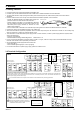
LBA Deadband function
The LBA may malfunction due to external disturbances. To
prevent malfunctioning due to external disturbance, LBA
deadband (LBD) sets a neutral zone in which LBA is not activated.
When the measured value (PV) is within the LBD area, LBA will
not be activated. If the LBD setting is not correct, the LBA will not
work correctly.
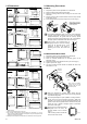
5.3 Changing Parameter Settings
Procedures to change parameter settings are shown below.
To store a new value for the parameter, always press the SET
key. The display changes to the next parameter and the new
value will be stored.
− A new value will not be stored without pressing SET key after
the new value is displayed on the display.
− After a new value has been displayed by using the UP and
DOWN keys, the SET key must be pressed within one minute,
or the new value is not stored and the display will return to the
PV/SV monitor screen.
Change the set value (SV)
Change the set value (SV) from 0 °C to 200 °C
1. Select the SV setting mode
Press the SET key at PV/SV monitor screen until SV setting
screen is displayed.
SV
CB100
PV
AT
SET R/S
OUT 1 OUT2 AL M1 ALM2
PV/SV monitor display
(PV/SV display mode)
SV
CB100
PV
AT
SET R/S
OUT1 OUT2 ALM1 ALM2
SV setting display
(SV setting mode)
2. Shift the high-lighted digit
Press the <R/S key to high-light the hundreds digit.
The high-lighted digit indicates which digit can be set.
SV
CB100
PV
AT
SET R/S
OUT 1 OUT2 AL M1 ALM2
SV
CB100
PV
AT
SET R/S
OUT1 OUT2 ALM1 ALM2
3. Change the set value
Press the UP key to change the number to 2.
SV
CB100
PV
AT
SET R/S
OUT 1 OUT2 AL M1 ALM2
SV
CB100
PV
AT
SET R/S
OUT1 OUT2 ALM1 ALM2
4. Store the set value
Press the SET key to store the new set value. The display returns
to the PV/SV monitor screen.
SV
CB100
PV
AT
SET R/S
OUT 1 OUT2 AL M1 ALM2
SV
CB100
PV
AT
SET R/S
OUT1 OUT2 ALM1 ALM2
PV/SV monitor display
(PV/SV display mode)
Change parameters other than the set value (SV)
The changing procedures are the same as those of example 2 to
4 in the above " Change the set value (SV)". Pressing the SET
key after the setting end shifts to the next parameter. When no
parameter setting is required, return the instrument to the PV/SV
display mode.
* TC and RTD inputs: 0.8 °C [°F] (fixed) Voltage/Current inputs: 0.8 % of span (fixed)
A
: During temperature rise: Alarm area
During temperature fall: Non-alarm area
B:
During temperature rise:
Non
-
alarm area
B: During temperature rise: Non-alarm area
During temperature fall: Alarm area
LBD differential gap*
Alarm area Alarm area
Non-alarm area
Set value (SV) LBD set value
Low High
A B