
Instruction manual


IMCB25-E3 5
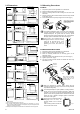
4. PARTS DESCRIPTION
(1)
CB100
CB100
R
KC
PV
SV
A
T
R/S
SET
OUT1 OUT2
A
LM1
A
LM2
(2)
(3)
(4) (5) (6) (7)
A
T
OUT1
R/S
PV
SET
CB500
R
KC
SV
OUT2
A
LM1
A
LM2
(2)
CB500
(1)
(3)
(4) (5) (6) (7)
PV
SV
A
T
OUT1
A
LM1
A
LM2
OUT2
CB400
R/S
SET
R
KC
(1)
(3)
(4)
(5) (6) (7)
CB400
(2)
PV
SV
A
T
OUT1
R/S
SET
OUT2
A
LM1
A
LM2
CB900
R
KC
(1)
(3)
(2)
(4) (5) (6)
(7)
CB700, CB900
5. SETTING
5.1 Operation Menu
This instrument returns to the PV/SV
display mode if no key operation is
performed for more than one minute.
Input type and input range display
This instrument immediately confirms the input type symbol and input range following power ON.
Example: When sensor type of input is K thermocouple.
(1)
Measured value (PV) display [Green]
Displays PV or various parameter symbols.
(2) Set value (SV) display [Orange]
Displays SV or various parameter set values (or
CT input value).
(3)
Indication lamps
Alarm output lamps (ALM1,ALM2) [Red]
ALM1: Lights when alarm 1 output is turned on.
ALM2: Lights when alarm 2 output is turned on.
Autotuning (AT) lamp [Green]
Flashes when autotuning is activated. (After
autotuning is completed: AT lamp will become
OFF)
Control output lamps (OUT1, OUT2) [Green]
OUT1: Lights when control output is turned on.*
OUT2: Lights when cool-side control output is
turned on.*
* Lamp indication becomes as follows for
current output.
For an output of less than 0 %: Extinguished
For an output of more than 100 %: Lit
For an output of more than 0 % but less than
100 %: Dimly lit.
(4)
(Set key)
Used for parameter calling up and set value
registration.
SET
(5)
(Shift & R/S key)
Shift digits when settings are changed.
Select the RUN/STOP function.
(6)
(DOWN key)
Decrease numerals.
(7)
(UP key)
Increase numerals.
R/S
To a
v
oid damage to the
instrument, never use a
sharp object to press keys.
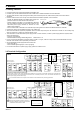
Symbol
PV
SV
PV
SV
Unit for input and SV display
(Celsius: °C, Fahrenheit: °F, Voltage/current input: no character shown)
Input type symbol *
Input range high
Input range low
Automatically
(
∗
): This input type is not displayed in the Z-1021 specification.
* Input Type Symbol Table
Symbol
Thermocouple (TC)
W5Re/
W26Re
U L
Voltage
(Current)
JPt
100
Pt
100
KJRSBETN
(
∗
)
Input type
RTD
(
∗
)
PL II
Power ON
PV/SV Display Mode
The controller will display the measured
value (PV) and the set value (SV).
The controller can be switched to RUN o
r
STOP mode (Factory set value: RUN).
PV/SV monitor
(RUN mode)
PV
SV
Press the <R/S key for 1 second.
SV
STOP character display
(STOP mode)
SV Setting Mode
SV setting
PV
SV
This is the mode used to set the SV.
Factory set value: 0 °C [°F] or 0.0 °C [°F]
Press the SET key
Press
the SET key
for 2 seconds.
Press
the <R/S key
while
pressing the
SET key.
Input type and Input range Display
Automatically (in 4 sec)
Parameter Setting Mode
This mode is used to set the parameters such as alarms, PID constants, etc. (See page 6.)
The following parameter symbols are displayed as the SET key is pressed.
SET key
Current transformer
(CT) input value 1
monitor
Control loop break
alarm (LBA) time
LBA deadband
A
larm 1 set value
(ALM1)
A
larm 2 set value
(ALM2)
Heater break alarm
(HBA) 1 set value
A
utotuning (AT)
Self-tuning (ST)
Proportional band
Integral time
Derivative time
A
nti-reset windup
Heat-side proportioning
cycle
Cool-side proportioning
band
Deadband
Cool-side proportioning
cycle
PV bias
Set data lock
Return to the first parameter
SET key
SET key
SET key
SET key
SET key
SET key
SET key
SET key
SET key
SET key
SET key
SET key
SET key
SET key
SET key
SET key
SET key
Parameters which are not related to existing functions on the controller are not displayed.
(CT1)
(AL1)
(AL2)
(HbA1)
(LbA)
(Lbd)
(ATU)
(STU)
(P)
(I)
(D)
(Ar)
(T)
(Pc)
(db)
(t)
(Pb)
(LCK)
Communication Setting Mode
This mode is used to set the communication parameters when specified. For details on protocol,
identifiers and communication setting mode, see the Communication Instruction Manual (IMCB03-E).