
Instruction manual


IMCB25-E3 3
3. WIRING
3.1 Wiring Cautions
• For thermocouple input, use the appropriate compensation wire.
• For RTD input, use low resistance lead wire with no difference in resistance between the three lead wires.
• To avoid noise induction, keep input signal wire away from instrument power line, load lines and power lines of other electric
equipment.
• If there is electrical noise in the vicinity of the instrument that could affect operation, use a noise filter.
- Shorten the distance between the twisted power supply wire
pitches to achieve the most effective noise reduction.
- Always install the noise filter on a grounded panel. Minimize
the wiring distance between the noise filter output and the
instrument power supply terminals to achieve the most
effective noise reduction.
- Do not connect fuses or switches to the noise filter output wiring as this will reduce the effectiveness of the noise filter.
• Power supply wiring must be twisted and have a low voltage drop.
• About four seconds are required as preparation time for contact output every time the instrument is turned on. Use a delay relay
when the output line, is used for an external interlock circuit.
• This instrument is not furnished with a power supply switch or fuses. Therefore, if a fuse or power supply switch is required, install
close to the instrument.
- Fuse type: Time-lag fuse
- Recommended fuse rating: Rated voltage 250 V Rated current: 1 A
• For the current input specification, a resistor of 250 Ω (±0.02 % ±10 ppm, 0.25 W or more) must be connected between the input
terminals. This resistor must be provided by the customer.
• Use the solderless terminal appropriate to the screw size.
- Screw size: M3 x 6
- Recommended tightening torque: 0.4 Nm [4 kgfcm]
• For an instrument with 24 V power supply, supply power from a SELV circuit.
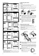
3.2 Terminal Configuration
A
larm outputPower supply
Control output
Input
Communication
NO: Normally open
NC: Normally closed
7
8
9
10
11
12
13
14
15
16
17
18
1
2
3
4
5
6
100 to 240V
A
C
24V
DC
24V
A
C
22
11
2
1
L
N
+
−
L
N
13
14
15
T/R(A)
T/R(B)
SG
RS-485
(Option)
CT input
Current
transformer input
18
17
CT1
(Option)
Alarm 1
Alarm 2
NO
A
LM1
A
LM2
7
8
9
NO
(Option)
+
−
TC
TC input
11
12
A
B
B
RTD
10
RTD input
11
12
+
−
IN
Voltage input
0 to 5 V DC
1 to 5 V DC
11
12
+
−
11
12
Current input
0 to 20 mA DC
4 to 20 mA DC
W, A action types
Relay contact
Voltage pulse
Current
Triac
NO
OUT2
NO
OUT1
3
4
5
6
OUT2
OUT1
+
+
−
−
3
4
5
6
OUT2
3
4
Triac out
5
6
OUT1
Triac out
Relay contact
Voltage pulse
Current
Triac
Trigger
F, D action types
NC
NO
OUT1
4
5
6
OUT1
+
−
6
5
Triac out
OUT1
5
4
OUT1
T2
T1
G
4
6
5
CB100
* Cautions for Communication terminal wiring:
Conduct wiring so that the power supply terminals (screw heads) do not touch the communication terminal lugs. Especially when
two lugs are connected to one communication terminal for the use of multidrop connection, much care should be exercised not to
touch the power supply terminals with the lugs.
It is recommended that the host computer communication line be isolated from the power supply and earth.
Power supply
Control output
NO: Normally open
NC: Normally closed
100 to 240V
A
C
24V
DC
24V
A
C
22
11
2
1
L
N
+
−
L
N
Communication
13
14
15
T/R(A)
T/R(B)
SG
RS-485
(Option)
Alarm output
Alarm 1
Alarm 2
NO
A
LM1
A
LM2
7
8
9
NO
(Option)
Input
+
−
TC
TC input
11
12
A
B
B
RTD
10
RTD input
11
12
+
−
IN
Voltage input
0 to 5 V DC
1 to 5 V DC
11
12
+
−
11
12
Current input
0 to 20 mA DC
4 to 20 mA DC
W, A action types
Relay contact
Voltage pulse
Current
Triac
NO
OUT2
NO
OUT1
3
4
5
6
OUT2
OUT1
+
+
−
−
3
4
5
6
OUT2
3
4
Triac out
5
6
OUT1
Triac out
Relay contact
Voltage pulse
Current
Triac
Trigger
F, D action types
NC
NO
OUT1
4
5
6
OUT1
+
−
6
5
Triac out
OUT1
5
4
OUT1
T2
T1
G
4
6
5
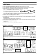
CB400
The terminal arrangement of CB500 is as shown in
the following diagram, but the terminal configuration
of CB500 is the same as that of CB400.
1
2
3
4
5
6
7
8
10
11
9
12
13
14
15
16
17
18
19
20
22
23
21
24
13 14
15 16 17 18 19 20 21 22 23 24
1
2
3 4 5 6 7 8 9 10 11 12
CT input
Current
transformer input
24
23
CT1
(Option)
OUT
Minimize
distance
Instrument
power
terminals
IN
Twist these leadwires
Shorten distance between
pitches
Instrument power
Noise filter