
Instruction manual


IMCB25-E3
2
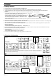
2.2 Dimensions
*1 Rubber (option)
*2 Up to four mounting brackets can be used.
For mounting of the instrument, panel thickness must be between 1 to 10 mm.
(When mounting multiple instruments close together, the panel strength should be
checked to ensure proper support.)
Waterproof and dustproof are not effective when instruments are closely spaced.
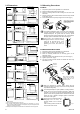
2.3 Mounting Procedures
CB100
1. Prepare the panel cutout as specified in 2.2 Dimensions.
2. Insert the instrument through the panel cutout.
3. Insert the mounting frame into the mounting from the rear of the
instrument.
4. Push the mounting frame forward until the frame is firmly secured
to the panel. (Fig.1)
5. Fix the instrument to the panel by using the two screws. (Fig.2)
The waterproof/dustproof option on the front of the instrument
conforms to IP66 when mounted on the panel. For effective
waterproof/dustproof, the gasket must be securely placed
between instrument and panel without any gap. If the gasket is
damaged, please contact RKC sales office or the agent.
If the hook in the mounting frame is
disengaged from the case, the mounting
frame can be removed (Fig.3). If the
instrument is fixed to the panel by
tightening the screws, first loosen the
screw.
CB400/CB500/CB700/CB900
1. Prepare the panel cutout as specified in 2.2 Dimensions.
2. Insert the instrument through the panel cutout.
3. Insert the mounting bracket into the mounting groove of the
instrument. (Fig.1)
4. Pull till click sounds to the direction shown by the arrow. (Fig.2)
5. Tighten up the screw. (Fig.3)
6. The other mounting bracket should be installed the same way
described in 3. to 5.
When the instrument is mounted, always secure with two
mounting brackets so that upper and lower mounting brackets
are positioned diagonally.
The waterproof/dustproof option (CB900: mounting bracket 4
pieces) on the front of the instrument conforms to IP65 when
mounted on the panel. For effective waterproof/dustproof, the
gasket must be securely placed between instrument and panel
without any gap. If gasket is damaged, please contact RKC
sales office or the agent.
If the hook in the mounting bracket is
disengaged from the case, the
mounting bracket can be removed
(Fig. 4).
If the mounting bracket is fixed with
screw, loosen these screws.
Mounting
frame
Fig.1
Fig.2
When using the mounting
screws, only turn one full
revolution after the screw
touches the panel.
When using the mounting
screws, only turn one full
revolution after the screw
touches the panel.
Fig. 3
Fig. 3
9.2
8.2 100
44.8
61.6
44.8
48
(
Unit: mm)
48
1
*
(
1
)
CB100
25
25
25
25
45
+0.6
45
+0.6
Individual mounting
0
0
L1
n
:
Number of controllers (2
≦
n
≦
6
)
+0.6
0
45
Close horizontal mounting
L1=(48
×
n-3
)
+0.6
0
9.2
8.2
1
*
100
(Unit: mm)
48
91.8
110.8
96
44.8
CB400
(
1
)
25
45
+0.6
0
30
92
+0.8
0
92
L1
+0.8
0
Individual mounting
Close horizontal mounting
n
:
Number of controllers (2
≦
n
≦
6
)
L1=(48
×
n-3
)
+0.6
0
L1
9.2
8.2
100
91.8
110.8
44.8
48
96
(Unit: mm)
1*
(
1
)
CB500
25
30 92
+0.8
0
Individual mounting
Close vertical mounting
n
:
Number of controllers (2
≦
n
≦
6
)
L1=(48
×
n-3
)
+0.6
0
+0.6
0
92
45
+0.8
0
9.2
8.2
100
72
86.8
72
67.8
67.8
(Unit: mm)
1
*
(
1
)
CB700
25
30
68
L1
+0.7
0
68
+0.7
0
68
+0.7
0
Individual mounting
Close horizontal mounting
n:Number of controllers (2
≦
n
≦
6
)
L1=(72
×
n-4
)
+0.7
0
9.2
96
96
91.8
8.2 100
91.8
110.8
CB900
(Uni t: mm)
2
*
25
30
Individual mounting
92
L1
n
:
Number of controllers (2
≦
n
≦
6
)
+0.8
0
Close horizontal mounting
92
+0.8
0
92
+0.8
0
L1=(96
×
n-4
)
+0.8
0
1
*
(
1
)
Screw
Fig.1
Fig.2
Fig. 4
Mounting
bracket