
Instruction manual


10 IMCB25-E3
7.4 Input Type Selection (SL1)
When any parameter setting is changed in the Initialization
Mode, check all parameter set values in SV Setting Mode
and Parameter Setting Mode.
Factory set value varies depending on the input type.
Set value Input type
0000 K
0001 J
0010 L
0011 E
0100 N
0111 R
1000 S
1001 B
4
1010 W5Re/W26Re
4
1011 PL II
0101 T
0110 U
Thermocouple
1
(TC)
1100 Pt100 Ω (JIS/IEC)
1101 JPt100 Ω (JIS)
RTD
1
1110 0 to 5 V DC
1110 0 to 10 V DC
2
1111 1 to 5 V DC
Voltage
1
1110 0 to 20 mA DC
1111 4 to 20 mA DC
Current
1, 3
1
Any input change in TC&RTD Group is possible. Any input change in
voltage¤t Group except for 0 to 10 V DC input is possible. No input
change between TC&RTD Group and voltage¤t Group is possible.
2
The input type of Z-1010 specification is fixed to 0 to 10 V DC due to the
hardware difference.
3
For the current input specification, a resistor of 250 Ω must be connected
between the input terminals.
4
W5Re/W26Re and B are not available with Z-1021 specification (Modbus
communication).
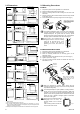
Change Settings
Example: Change the input type from “K” to “J”
1. Set “Cod” to 0000, and press the SET key. The display will
go to SL1.
Input type selection
Initialize code selection display
SV
PV
SV
PV
2. Press the UP key to change the number to 1.
SV
PV
3. Press the SET key to store the new set value. The display
goes to the next parameter.
7.5 Temperature Unit and Cooling Type
Selection (SL2)
Inappropriate settings may result in malfunction.
Control type between Heat Only and Heat/Cool cannot be
changed by this parameter.
Factory set value varies depending on the instrument specification.
Description
Set
value
Temperature
unit
Cooling type selection
0000 °C Air cooling (A type) or Heat only type (F, D type)
0001 °F Air cooling (A type) or Heat only type (F, D type)
0010 °C Water cooling (W type)
0011 °F Water cooling (W type)
Change Settings
Example: Change the temperature unit of the Heat only type
from “°C (0000)” to “°F (0001)”
1. Press the SET key until SL2 is displayed.
2. Press the UP key to change the number to 1.
SV
PV
SV
PV
3. Press the SET key to store the new set value. The display
goes to the next parameter.
7.6 Alarm 1 [ALM1] Type Selection (SL4)
Alarm 2 [ALM2] Type Selection (SL5)
If the alarm function is not provided with the instrument when
shipped from the factory, no alarm output is available by changing
SL4 and/or SL5.
SL4 is set to 0000 in the following cases.
• When the instrument does not have ALM1 output
• When Control Loop Break Alarm (LBA) is provided and
assigned to ALM1
• When the SV alarm is provided and assigned to ALM1
SL5 is set to 0000 in the following cases.
• When the instrument does not have ALM2 output
• When Control Loop Break Alarm (LBA) is provided and
assigned to ALM2
• When the SV alarm is provided and assigned to ALM2
• When the Heater Break Alarm (HBA) is provided
• When the instrument has Z-168 specification
Factory set value varies depending on the instrument specification.
Set value
Details of setting
0000 No alarm
0001 Deviation high alarm
0101 Deviation low alarm
0010 Deviation high/low alarm
0110 Band alarm
0011 Process high alarm
0111 Process low alarm
1001 Deviation high alarm with hold action *
1101 Deviation low alarm with hold action *
1010 Deviation high/low alarm with hold action *
1011 Process high alarm with hold action *
1111 Process low alarm with hold action *
* Hold action:
When Hold action is ON, the alarm action is suppressed at start-up or the
control set value change until the measured value enters the non-alarm range.
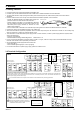
Alarm action type
Both of the Alarm 1 and Alarm 2 outputs of this instrument are
turned on when burnout occurs regardless of any of the following
actions taken (High alarm, low alarm, etc.). In addition, when
used for any purposes other than these alarms (event, etc.),
specify the Z-124 specification (not to be forcibly turned on).
( : SV : Alarm set value)
Deviation high alarm
Band alarm
Process low alarm
Deviation low alarm
*(Alarm set value is less than 0.)
OFF ON
Low High
PV
*(Alarm set value is less than 0.)
OFF ON
PV
Low High
OFF ON
PV
Low High
OFF ON
PV
Low High
OFF ON ON
PV
Low High
OFF OFF ON
PV
Low High
OFF ON
PV
Low High
ON OFF
PV
Low High
*(Alarm set value is greater than 0.)
*(Alarm set value is greater than 0.)
Process high alarm
Deviation high/low alarm
Change Settings
Example: Change the ALM1 type from “Deviation high alarm
(0001)” to “Deviation low alarm (0101)”
1. Press the SET key three times at SL1 until SL4 is displayed.
2. Press the <R/S key to high-light the hundreds digit.
3. Press the UP key to change the number to 1.
SV
PV
SV
PV
4. Press the SET key to store the new set value. The display
goes to the next parameter.