
Instruction manual


IMCB14-E1
23
6. MESSAGE FORMAT
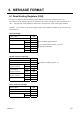
6.1 Read Holding Registers [03H]
The query message specifies the starting register address and quantity of registers to be read.
The contents of the holding registers are entered in the response message as data, divided into two
parts: the high-order 8 bits and the low-order 8 bits, arranged in the order of the register numbers.
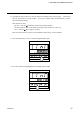
Example: The contents of the three holding registers from 0000H to 0002H are the read out from
slave address 2.
Query message
Slave address 02H
Function code 03H
Starting number High 00H
Low 00H
Quantity High 00H
Low 03H
CRC-16 High 05H
Low F8H
Normal response message
Slave address 02H
Function code 03H
Number of data 06H
First holding High 00H
register contents Low 64H
Next holding High 00H
register contents Low 00H
Next holding High 00H
register contents Low 00H
CRC-16 High 44H
Low 4DH
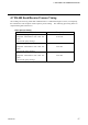
Error response message
Slave address 02H
80H Function code 83H
Error code 03H
CRC-16 High F1H
Low 31H
First holding register address
The setting must be between 1 and 125
(0001H and 007DH)
Number of holding registers u 2