Digital Controller CB100/CB400 CB500/CB700 CB900 [Z-1021] MODBUS Communication Instruction Manual ® RKC INSTRUMENT INC.
z Modbus is a registered trademark of Schneider Electric. z Company names and product names used in this manual are the trademarks or registered trademarks of the respective companies. All Rights Reserved, Copyright ¤ 1999, RKC INSTRUMENT INC.
Thank you for purchasing the RKC instrument. In order to achieve maximum performance and ensure proper operation of your new instrument, carefully read all the instructions in this manual. Please place this manual in a convenient location for easy reference. SYMBOLS WARNING : This mark indicates precautions that must be taken if there is danger of electric shock, fire, etc., which could result in loss of life or injury.
CAUTION z This is a Class A instrument. In a domestic environment, this instrument may cause radio interference, in which case the user may be required to take adequate measures. z This instrument is protected from electric shock by reinforced insulation. Provide reinforced insulation between the wire for the input signal and the wires for instrument power supply, source of power and loads. z This instrument is designed for installation in an enclosed instrumentation panel.
CONTENTS Page 1. OUTLINE ..............................................................................1 2. SPECIFICATIONS ................................................................2 3. WIRING.................................................................................3 4. COMMUNICATION SETTINGS............................................6 4.1 4.2 4.3 4.4 4.5 4.6 4.7 Communication Setting Mode .........................................................................
Page 7. DATA CONFIGURATION....................................................26 7.1 Data Configuration ........................................................................................26 7.2 Data Processing Precautions ........................................................................27 7.3 Communication Data List ..............................................................................28 8. TROUBLESHOOTING .......................................................
1. OUTLINE This manual describes the specifications, wiring instructions and communication settings for CB100/CB400/CB500/CB700/CB900 Z-1021 with Modbus communication protocol. Slave side RS-485 MODBUS Host computer or PLC etc.
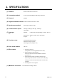
2.
3. WIRING ! WARNING To prevent electric shock or instrument failure, turn off the power before connecting or disconnecting the instrument and peripheral equipment. Terminal number and signal details CB100/CB400/CB500/CB900 Terminal No. Signal name Name 13 SG 14 T/R(A) Send data/Receive data 15 T/R(B) Send data/Receive data Terminal No.
3. WIRING Connection to the RS-485 port of the master The master has a built-in circuit to transfer send/receive data alternatively. RS-485 Paired wire Master SG T/R(A) SG T/R(A) T/R(B) T/R(B) Slave y y y RD (RXD):Receive data Send/Receive transfer signal Shielded twisted pair wire SG SD (TXD):Send data SD (TXD) and RD (RXD): Negative logic T/R(A) T/R(B) Slave (31 max.) Use a terminal resistor with a combined resistance of 100 : on the last controller.
3. WIRING Connection with up to 31 slaves and one master Master Master RS-232C RS-485 RS-232C/RS-485 converter RS-485 or BRA-100B-2 BRA-100B-2 BRA-100B-2 RS-485 Slave address example 1 2 Slaves 3 4 Slaves 29 30 31 Slaves For all pertinent details on the RS-232C/RS-485 converter and junction branch box (BRA100B-2), see the respective instruction manuals.
4. COMMUNICATION SETTINGS To establish communication parameters between master and slave, it is necessary to set the slave address, communication speed, data configuration and interval time on each slave in the communication mode. The CB900 controller will be used as an example, but the same instructions apply to all CB Series controllers with Modbus protocol. 4.1 Communication Setting Mode 1.
4. COMMUNICATION SETTINGS 4.2 Select Communication Parameters To select parameters in communication setting mode, press the SET key. The parameters are displayed and sequenced in the order of slave address, Add, communication speed, bPS, data configuration, bIT and interval time set value, InT. Display flowchart Power On Input type and input range display Display changes automatically PV/SV display mode (Display for approx. 4 sec) Press the SET key.
4. COMMUNICATION SETTINGS 4.3 Slave Address Setting The slave address must be set before Modbus communication can begin. The slave address number is set with numbers from 1 to 99. The factory set value is 0 and two-way communication is not possible when the address is 0. Symbol Name Slave address Setting range 1 to 99* Description Set the controller slave address. Factory set value 0 Add * Two-way communication is not possible when the address is 0.
4. COMMUNICATION SETTINGS 2. Press the UP key to enter 5 at the first digit from the right. PV SV AT OUT1 OUT2 ALM1 ALM2 SET R/S 3. Press the
4. COMMUNICATION SETTINGS 4.4 Communication Speed Setting The communication speed of 2400bps, 4800bps, 9600bps or 19200bps is set with numbers from 0 to 3. To change the number of the digit, press the UP or DOWN key. Symbol Name Communication speed bPS Setting range 0 : 2400 bps 1 : 4800 bps 2 : 9600 bps 3 : 19200 bps Description Select the communication speed Factory set value 2 Set the same communication speed for both the slave and the master.
4. SETTING FOR COMMUNICATION 2. Press the DOWN key to enter 1 (4800 bps) at the first digit from the right. PV SV AT OUT1 OUT2 ALM1 ALM2 SET R/S 3. Press the SET key to store the new communication speed. the next communication parameter, bIT.
4. SETTING FOR COMMUNICATION 4.5 Data Configuration Setting The data configuration shown below is set with numbers from 1 to 3. digit, press the UP or DOWN key. Symbol Name Data configuration bIT Setting range 0, 6 or 7 See Data To change the number of the Description Select data configuration during communication Factory set value 0 Configuration Table Data configuration table Setting Data bit 0 8 1 to 5 Parity bit Stop bit None 1 Do not set 1 to 5. Malfunction may result.
4. SETTING FOR COMMUNICATION Setting procedure Example: Setting the data configuration to 6: 8 data bits, even parity and 1 stop bit. 1. Go to the communication setting mode so that slave address, Add, is displayed. key until the data configuration symbol, bIT, appears. Press the SET PV SV AT OUT1 OUT2 ALM1 ALM2 SET R/S Data configuration 2. Press the UP key to enter 6 at the first digit from the right. PV SV AT OUT1 OUT2 ALM1 ALM2 SET R/S 3.
4. SETTING FOR COMMUNICATION 4.6 Interval Time Setting The interval time from 0 to 250 ms is set with numbers from 0 to 150. To shift the digit, press the
4. SETTING FOR COMMUNICATION 2. Calculate the interval time set value by using the formula on the previous page. The interval time set value must be a whole number. If you get a number with a decimal fraction, round to the nearest whole number. Interval time set value: 250 ms y 1.666 ms 150 (Round to the nearest whole number) The actual interval time re-calculated by using the interval time set value, 150: 150 u 1.666 ms 249.9 (Approx.
4. SETTING FOR COMMUNICATION 5. Press the UP key to enter 5 at the second digit from the right. PV SV AT OUT1 OUT2 ALM1 ALM2 SET R/S 6. Press the
4. SETTING FOR COMMUNICATION 4.7 RS-485 Send/Receive Process Timing The sending and receiving of RS-485 communication is conducted through two wires; consequently, the transmission and reception of data requires precise timing. The following processing times are required during data send/receive. Slave process timing Procedure details Read holding registers [03H] IMCB14-E1 Time (ms) Response transmission time after the slave receives the query message Preset single register [06H] 13 ms max.
5. MODBUS PROTOCOL The master controls communication between master and slave. A typical message consists of a request (query message) sent from the master followed by an answer (response message) from the slave. When master begins data transmission, a set of data is sent to the slave in a fixed sequence. When it is received, the slave decodes it, takes the necessary action, and returns data to the master. 5.
5. MODBUS PROTOCOL 5.2 Function Code z Function code contents Function code (Hexadecimal) Function 03H Read holding registers 06H Preset single register 08H Diagnostics (loopback test) Contents Measured value (PV), alarm status, current transformer input, etc. Set value (SV), alarm set value, PID constants, PV bias, etc.
5. MODBUS PROTOCOL 5.4 Slave Responses (1) Normal response z In the response message of the Read Holding Registers, the slave returns the read out data and the number of data items with the same slave address and function code as the query message. z In the response message of the Preset Single Register, the slave returns the same message as the query message. z In the response message of the Diagnostics (loopback test), the slave returns the same message as the query message.
5. MODBUS PROTOCOL 5.5 Calculating CRC-16 The Cyclic Redundancy Check (CRC) is a 2 byte (16-bit) error check code. After constructing the data message, not including start, stop, or parity bit, the master calculates a CRC code and appends this to the end of the message. The slave will calculate a CRC code from the received message, and compare it with the CRC code from the master. If they do not coincide, a communication error has occurred and the slave does not respond.
5. MODBUS PROTOCOL The flow chart of CRC-16 START FFFFH o CRC Register CRC Register next byte of the message o CRC Register 0on Shift CRC Register right 1 bit Carry flag is 1 No Yes CRC Register A001H o CRC Register n+1on No n!7 Yes No Is message complete ? Yes END The symbol indicates an exclusive OR operation. The symbol for the number of data bits is n.
6. MESSAGE FORMAT 6.1 Read Holding Registers [03H] The query message specifies the starting register address and quantity of registers to be read. The contents of the holding registers are entered in the response message as data, divided into two parts: the high-order 8 bits and the low-order 8 bits, arranged in the order of the register numbers. Example: The contents of the three holding registers from 0000H to 0002H are the read out from slave address 2.
6. MESSAGE FORMAT 6.2 Preset Single Register [06H] The query message specifies data to be written into the designated holding register. The write data is arranged in the query message with high-order 8 bits first and low-order 8 bits next. Only R/W holding registers can be specified. Example: Data is written into the holding register 0006H of slave address 1.
6. MESSAGE FORMAT 6.3 Diagnostics (Loopback Test) [08H] The master's query message will be returned as the response message from the slave. checks the communication system between the master and slave.
7. DATA CONFIGURATION 7.1 Data Configuration The numeric range of data used in Modbus protocol is 0000H to FFFFH. the setting range is effective. Only the set value within FFFFH represents -1. Data processing with decimal points ■ Data with decimal points The Modbus protocol does not recognize data with decimal points during communication.
7. DATA CONFIGURATION ■ Data whose decimal point's presence and/or position depends on input range The position of the decimal point changes depending on the input range type because the Modbus protocol does not recognize data with decimal points during communication. The following data can have one of three decimal point positions: z No decimal point z One decimal place z Two decimal places The input range for voltage/current input is fixed at 0.0 to 100.0%. For details, see Input Range Table 2 on P.34.
7. DATA CONFIGURATION 7.3 Communication Data List The communication data list summarizes data addresses (holding register numbers), names, attributes, setting ranges and factory set values.
7. DATA CONFIGURATION Continued from the previous page.
7. DATA CONFIGURATION Continued from the previous page. (Attribute Address Attribute Name RO: Read only R/W: Read and Write) Factory Data range or item description set value 18H Set data lock function R/W 0 to 7 19H RUN/STOP function R/W 0: RUN 1: STOP *1 For the current transformer input 2 function, Z-168 specification is required. *7 0 0 *2 For a unit without Z-168 specification, the read data is 0.
7.
7. DATA CONFIGURATION Continued from the previous page. Input type Input range E N T Thermocouple (TC) PL II U L 32 0 to 800 qC 0 to 1000 qC 0 to 1600 qF 0 to 1832 qF 0 to 1200 qC 0 to 1300 qC 0 to 2300 qF 0 to 2372 qF -199.9 to +400.0 qC -199.9 to +100.0 qC -100.0 to +200.0 qC 0.0 to 350.0 qC -199.9 to +752.0 qF -100.0 to +200.0 qF -100.0 to +400.0 qF 0.0 to 450.0 qF 0.0 to 752.0 qF 0 to 1300 qC 0 to 1390 qC 0 to 1200 qC 0 to 2400 qF 0 to 2534 qF -199.9 to +600.0 qC -199.9 to +100.0 qC 0.
7. DATA CONFIGURTION Continued from the previous page. Input type *1 *2 Input range -199.9 to +649.0 qC -199.9 to +200.0 qC -100.0 to +50.0 qC -100.0 to +100.0 qC -100.0 to +200.0 qC 0.0 to 50.0 qC 0.0 to 100.0 qC 0.0 to 200.0 qC 0.0 to 300.0 qC Pt100 : 0.0 to 500.0 qC -199.9 to +999.9 qF -199.9 to +400.0 qF -199.9 to +200.0 qF RTD -100.0 to +100.0 qF -100.0 to +300.0 qF 0.0 to 100.0 qF 0.0 to 200.0 qF 0.0 to 400.0 qF 0.0 to 500.0 qF -199.9 to +649.0 qC -199.9 to +200.0 qC -100.0 to +50.0 qC -100.
7. DATA CONFIGURATION Input Range Table 2 Input type Input range DC 0 to 5 V DC 0 to 10 V* DC 1 to 5 V Current input DC 0 to 20 mA (mA) DC 4 to 20 mA * For this voltage range, Z-1010 specification is required. Code Input Range Voltage input (V) 34 0. 0 to 100.
8. TROUBLESHOOTING ! WARNING To prevent electric shock or instrument failure, always turn off the system z power before replacing the instrument. To prevent electric shock or instrument failure, always turn off the power z before mounting or removing the instrument. To prevent electric shock or instrument failure, do not turn on the power until z all the wiring is completed. To prevent electric shock or instrument failure, do not touch the inside of the z instrument.
8. TROUBLESHOOTING Continued from the previous page. Symptom Probable cause Solution Error code 1 Function code error (An unsupported function code was specified) Confirm the function code Error code 2 Written to read only data. Confirm the register address of holding Any address other than 0000H to 0019H is specified.
The 1st edition: Sep.
RKC INSTRUMENT INC. HEADQUARTERS: 16-6, KUGAHARA 5-CHOME, OHTA-KU TOKYO 146-8515 JAPAN PHONE: 03-3751-9799 (+81 3 3751 9799) E-mail: info@rkcinst.co.jp FAX: 03-3751-8585 (+81 3 3751 8585) IMCB14-E1 SEP.