
Instruction manual


2. PROCEDURE FOR SETTING
IMCB04-E2
8
SV
PV
The details of parameters in each initialize code group are described in the following.
2.3 Details of parameters in initialize code 0 (Cod = 0)
(1) SL1 (Input type selection)
Conduct the setting so that it matches the instrument specification (input type). If the
setting is changed, always re-set the setting limits (SLH and SLL). (See P.17, 18)
Factory set value varies depending on the input type.
Set value Input type
0000 K
0001 J
0010 L
0011 E
0100 N
0111 R
1000 S
1001 B
1010 W5Re/W26Re
1011 PL II
0101 T
0110 U
Thermocouple input
(TC)
*2
1100
Pt100 Ω (JIS/IEC)
1101
JPt100 Ω (JIS)
RTD input
*2
1110 0 to 5 V DC
1111 1 to 5 V DC
Voltage input
*2
1110 0 to 20 mA DC
1111 4 to 20 mA DC
Current input
*1, *2
*1 : For the current input specification, a resistor of 250 Ω must be connected between
the input terminals.
*2 : No input type (TC/RTD input to voltage/current input or voltage/current input to
TC/RTD input) cannot be changed.
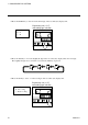
CAUTION
Measured value (PV) display unit shows parameter No.
Input the numerical value in the set value (SV)
*Note that the relevant digit
used differs depending on the
The figure at the above is for selects the "Water cooling" in "SL2 (Engineering unit and cooling type selection)".
0
1
Set value
Parameter display position