
Instructions
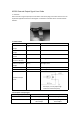

4. Examples of wiring diagrams for these mode
K3 Pro provides S1 and S2 signal output modes. This section introduces common wiring examples
in S1 and S2 mode. This article does not make any guarantees for the circuit, only for design
reference. Users need to modify according to their actual use.
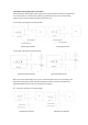
4.1 S1 mode, output signal connected to MCU
Output signal forward Output signal reverse
4.2 S1 mode, output port connected to load
Abnormal temperature ON Normal temperature ON
Note: Due to the limited output current, users need to design the drive circuit according to the
load power requirements. When inductive/capacitive loads are connected, the influence of
inductive/capacitive loads on the circuit should be considered.
4.3 S2 mode, output port connected to MCU
Positive pulse direction Negative pulse direction