
User`s manual


4
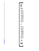
Controls and Connectors
Front Panel
1. Write Button – Hold this button for three seconds to save the current settings to memory. The LEDs will flash to
confirm.
2. Function Switch Buttons – These buttons turn function switches 1 through 8 on and off. The LED above each
button is lit when the corresponding function switch is on.
The Function Switches are used to control channel switching and other features of an amplifier connected to the RG-16
via the Amp 1 and/or Amp 2 jacks.
3. Power LED – Lights when the RG-16 is powered on.
4. Audio Loop Buttons - These buttons turn audio loops 1 through 8 on and off. The LED above each button is lit
when the corresponding audio loop is on.
5. Input Jack – This jack is connected to the rear panel From Front jack (8), and will pass a mono or stereo signal
through to that connector.
Rear Panel
6. Buffer In – Input to the audio buffer circuit. Using long cables or many effects may degrade the guitar signal, causing
it to lose clarity and definition. The audio buffer is used to “strengthen” the guitar signal and preserve sound quality.
The effect may vary from subtle to significant, depending on the length and quality of cables and type of effects used in
your rig.
7. Buffer Out – Output from the audio buffer circuit.
8. From Front – Signal from the front panel Input Jack (5) appears at this jack.
9. Input – Input to audio loops 1 through 4.
About Audio Loops 1 through 4
Audio Loops 1 through 4 are connected in series. Each loop is connected internally to the next. When a loop is off, the
Send and Receive jacks for that loop are bypassed. The audio signal passes through unchanged. Turning the loop on
routes the guitar signal through the send jack and connects the return jack to the next loop.
10. Send 1 through 4 – Connect your effects inputs here. When the loop is on, the audio signal will be output at the
send jack. When the loop is off, the send jack is grounded and no signal is output.
11. Return 1 through 4 – Connect your effects outputs here. When the loop is on, signal sent to these jacks will be
passed through to the next loop. If nothing is plugged in to the Return jack, the loop is bypassed and activating the
loop will have no effect.
12. Tuner Out – This is an additional output that can be used to connect a tuner. It is connected to the buffer output,
so there is only signal present here if the buffer is in use.
13. Output – Output from loops 1 through 4.