
User`s manual


5
About Audio Loops 5 through 8
Audio loops 5 through 8 are fully independent and not connected to each other in any way. Each loop has its own
discrete input and output. When a loop is off, the Send and Receive jacks for that loop are bypassed, and audio signal
passes unchanged from loop input to loop output. When a loop is on, the loop input is connected to the Send jack, and
the loop output is connected to the Return jack.
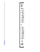
14. Input (5 through 8) – Signal input to the corresponding audio loop.
15. Send/NC (5 through 8) – Connect your effects inputs here. When the corresponding loop is on, audio signal will
be output at this jack. When the corresponding loop is off, this jack is grounded and no signal is output. (NOTE: This jack
can also be used as a Normally Closed function switch.)
16. Output/NO (5 through 8) – Signal output from the corresponding audio loop. (NOTE: this jack can also be used
as a Normally Open function switch.)
17. Return (5 through 8) – Connect your effects outputs here. When the corresponding loop is on, audio signal
feeding this output will be passed through to the loop output. If nothing is plugged into the Return jack, the loop is
bypassed and activating the loop will have no effect.
18. Amp 1 – Connect an amplifier interface cable from this jack to the footswitch jack of your amplifier. This
connection enables the RG-16 to control all the footswitch-accessible functions of your amplifier.
19. Amp 2 – Connect a second amplifier interface cable from this jack to the footswitch jack of a second amplifier. This
is particularly useful for a stereo rig, where you are using two identical amplifiers, or in an A/B rig, where you have two
amps, but are using only one at a time.
Important: Note that Amp 1 and Amp 2 jacks are switched in unison. Any function switching affects both Amp jacks
simultaneously. For example, turning Function Switch 1 on will turn that designated function on for both Amp 1 and
Amp 2.
20. MIDI Out – MIDI commands and data dumps are sent from this output.
21. MIDI Thru – Any MIDI commands sent to the MIDI In port (22) are output unchanged through this output.
22. MIDI In – Connect your MIDI footswitch (or controller) here to send incoming MIDI commands to the RG-16.
NOTE: If your MIDI footswitch supports phantom power, you can connect a 7-pin MIDI cable here and the RG-16 will
provide phantom power to the footswitch. Phantom power is supplied by the AC adapter that powers the RG-16. If you
use a 9VAC adapter to power the RG-16, the phantom power output will be 9VAC. If you use a 12VDC adapter, the
phantom power output will be 12VDC.
23. Power – Connect a 9VAC, 1 Amp (or 12VDC, 1 Amp) power supply here.
Important: Note that the RG-16 uses a 9 Volt AC or 12 Volt DC power supply. Do NOT connect any other power supply
to the unit. Many power supplies are very similar in appearance. Connecting the wrong power supply to the RG-16 can
damage the unit and void your warranty.