VT.3® WATER BOILER INSTALLATION & MAINTENANCE MANUAL Models (1500, 1800, 2000) WB 250A-IF Installation and service must be performed by a qualified service installer, service agency or the gas supplier. IMPORTANT: THIS MANUAL CONTAINS INFORMATION REQUIRED FOR INSTALLATION, OPERATION AND MAINTENANCE OF THIS EQUIPMENT. READ AND FOLLOW THE INFORMATION IN THIS MANUAL AND ALL OTHER PROVIDED INSTRUCTIONS, LABELS AND MARKINGS BEFORE INSTALLING, OPERATING OR SERVICING THIS UNIT.
TABLE OF CONTENTS 1. 2. 3. 4. 5. 6. 7. 8. Safety Considerations Product Description Boiler Installation 3.1 Checking Equipment Before You Install 3.2 Codes 3.3 Electrical Requirements 3.4 Location 3.5 Service Clearances 3.6 Clearances to Combustible Surfaces General Piping Guidelines 4.1 Inlet and Outlet Connections 4.2 Supply and Return Piping 4.3 Temperature Control Sensor (Install in system return piping) 4.4 Filling the Boiler Gas Supply Piping 5.1 Inlet Gas Pressure 5.2 Manifold Gas Pressure 5.
9. 10. 11. 12. 13. 14. 15. 16. TempTrac Controller Panel 9.1 Principle of Operation 9.2 Upper LED Readout 9.3 Lower LED Readout 9.4 Control Buttons 9.5 Modulation Firing Sequence 9.6 To View the Setpoint 9.7 To Change the Setpoint 9.8 To Change Other Parameters 9.9 LED Display Alarm Messages Boiler Control Interface 10.1 If BMS is to Provide Remote On/Off Control Only 10.2 If BMS Provides Modulation Control Through a 4 to 20 milliamp 10.3 MODBUS Application for TempTrac 10.
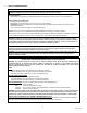
1. SAFETY CONSIDERATIONS WARNING: If the information in the supplied manual(s) is not followed exactly, a fire, explosion or exposure to hazardous materials may result, causing property damage, personal injury or death. FOR YOUR SAFETY • Do not store or use gasoline or other flammable vapors or liquids in the vicinity of this or any other appliance. WHAT TO DO IF YOU SMELL GAS • Do not try to light any appliance. • Do not touch any electric switch; do not use any phone in your building.
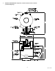
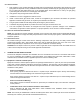
2 PRODUCT DESCRIPTION Component, Controls and Connection Locations (Locations May Vary) 5 34-53 08/14
3 BOILER INSTALLATION 3.1 Checking Equipment Before You Install Inspect the unit completely upon receipt from the freight carrier before signing the bill of lading. Inspect the appliance and all accompanying parts for signs of impact or mishandling. Verify the total number of pieces shown on packing slips with those actually received. Contact the freight carrier immediately if any damage or shortage is detected. 3.
4 GENERAL PIPING GUIDELINES Consult factory for piping of hybrid boiler systems that contain both condensing and non-condensing boilers. 4.1 Inlet and Outlet Connections The connection to the unit marked “Inlet” on the header connects to the return from the system (water to be heated). The connection on the header marked “Outlet” connects to the supply side of the system (hot water out of the unit). 4.
4.4 Filling The Boiler 1. Fill the system with water. To be sure that the unit is not “air bound,” open the relief valve. Leave the valve open until a steady flow of water is observed. Close valve and complete filling the system. 2. In hard water areas, water treatment should be used to reduce introduction of minerals into the system. Excessive buildup of minerals in the heat exchanger can cause a non-warrantable failure. 3. Make sure there are no system leaks. DO NOT use petroleum based stop-leak products.
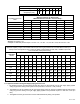
CONVERT FITTINGS TO EQUIVALENT STRAIGHT PIPE Diameter Fitting (inches) Equivalent Length of Straight Pipe (feet) Equivalent Feet From Meter 25 40 60 80 100 125 150 175 200 ¾" 1" 1¼" 1½" 2" 3" 2' 2' 5' 10' 14' 20' 3' 4' 4" 5" SINGLE UNIT INSTALLATION SUGGESTED PIPE SIZE Maximum Capacity for Natural Gas* MBTU/HR Based on 0.5" W.C.
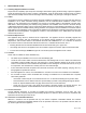
5.5 Gas Connection 1. Safe operation of unit requires adequate gas supply with the required static and dynamic (flow) pressures. Actual piping selection depends on many variables that must be carefully considered by the gas piping system designer. Do not select gas pipe sizes based only on the supplied tables. These tables are for use by the gas piping system designer as a reference in checking pipe size selections. 2. Gas pipe size may be larger than boiler connection. 3.
WARNING – Adequate clean combustion air must be provided to the appliance. Under no circumstances should the appliance ever be under a negative pressure. Particular care should be taken when exhaust fans, compressors, air handling units, etc. may rob air from the appliance. The combustion air supply must be completely free of any chemical or fumes, which may be corrosive to the appliance.
Vertical Remote Air (recommended) Horizontal Remote Air (allowed) 6.5 Remote Air Consideration for Combined Remote Air Ducting Each boiler MUST have separate intake piping. Consult factory for common air intake assistance. 7 VENTING 7.
• A barometric damper (draft control) is supplied with all models, unless the CAT34 option is ordered. If the boiler was ordered with the CAT34 option, but is going to be installed with a Category I vent system, a barometric damper and vent size increaser (for attachment of the vent connector to the boiler vent connection) sized to match the required Category I vent diameter, must be obtained from Riverside Hydronics.
• Obtain the correct adapter for attaching and sealing to the VT3 5-7/8 inch vent connection outlet from the manufacturer of the listed Category III or IV venting system being installed. Attach this adapter to the VT3 vent connection outlet following the instruction provided by the adapter’s manufacturer. • Follow the Category III or Category IV vent manufacturers’ instruction for installation, sealing and support of their vent system.
7.3.2 Vertical or Horizontal Vent Termination 1. The vent terminal must have a minimum clearance of 4 feet (1.22 m) horizontally from, and in no case be located above or below, electric meters, gas meters, regulators and relief equipment. 2. The vent cap must terminate at least 3 feet (0.91 m) above any forced air inlet within 10 feet (3.05 m). 3. The vent shall terminate at least 4 feet (1.22 m) below, 4 feet (1.22 m) horizontally from or 1 foot (0.
8 8.1 OPERATING AND SAFETY CONTROLS Operating Temperature Control An adjustable digital operating control is located in the front control panel. See TempTrac Electronic Controller Panel in this manual for more information. 8.2 High Water Temperature Limit Control The boiler is equipped with adjustable limit and high limit controls to control the maximum discharge water temperature. These controls are located inside the control cabinet and are accessed by removing the bottom cover.
9 TEMPTRAC™ ELECTRONIC CONTROLLER PANEL 9.1 Principle Of Operation The boiler operates to satisfy the setpoint of the TempTrac digital control whose sensor is located in the return line of a Hydronic system. Demand (flow) will typically create a drop in temperature, thus activating the Centauri to add heat to the system. This setpoint is the highest temperature the appliance permits any firing to occur. 9.
LABEL DEFAULT VALUE NET TEMPERATURE NET TEMP DETERMINED BY St1 165 165°F LED display value Hy1 -8 157°F St1 + Hy1 St4 -10 155°F St1 + St4 SR -10 145°F St1 + St4 + SR • St1: The system’s desired maximum setpoint (when all firing ceases). This is the temperature setpoint of the appliance. The factory setpoint is 165°F. • Hy1: The differential from St1. This is the Burner-On threshold. The burner Call-For-Heat is initiated and establishes the firing rate at low fire.
• D: The unit will remain in modulation until the sensed temperature rises above 155°F (St4). The firing rate returns to low fire. Modulation will only reactivate when return loop temperature drops to 155°F. • E to F: Low fire is maintained if the return loop temperature ranges between 155° and 165°F. • F: This firing pattern will continue until the temperature reaches the “Burner OFF” threshold of 165°F (St1) and shuts off. 9.
ALARM MESSAGE “P1” TP1 probe failure “P2” TP2 probe failure “P3” TP3 probe failure “HA” “LA” HP LP Mn1 Mn2 Mn3 “rtc” “rtF” 10 CAUSE High temperature limit setpoint exceeded Low temperature alarm High gas pressure alarm Low gas pressure alarm Maintenance alarm for output 1 Maintenance alarm for output 2 Maintenance alarm for output 3 The real time clock has lost its setting Real time clock failure RESULTS OF ALARM CONDITION Inlet temperature sensor is not connected or is reading incorrectly.
10.4 Making BMS/BAS remote connections for analog and binary (on/off) signals A terminal strip for the remote connection is located behind the hinged control panel at the top of the cabinet and is accessed by removing the bottom cover and then removing the screws at the top of the hinged cover. IMPORTANT: Do not use single strand bell wire for remote field connections to terminals R1-R2 and C1-C2. Use only multi-strand copper wire.
Display St1 tt rr2 rr1 tt2 Ht2 Parameter Description Temperature at the return boiler loop that activates /deactivates boiler firing Outdoor air temperature where outdoor reset is activated and deactivated Outdoor air temperature range through which St1 setting will be adjusted Maximum increase of St1 setting when outdoor reset is activated Outdoor air temperature where boiler is de-energized Differential from tt2 required to reenergize the boiler Value 165° F 30° F -20° F 10° F 100° F -10° F • Outside
3. Call For Heat - If the TempTrac operating control senses a call-for-heat condition: a. The High Gas Pressure and low Gas Pressure Switch (both optional) are energized and their safe condition is proved. b. The thermostat contact on the Fenwal Flame Safeguard Control is energized. c. The flame control will then verify the Airflow-Proving Switch is in the open position, which must exist before the blower is powered. d. Energizing the blower should close the airflow proving switch.
9.
12.5 Startup Procedure 1. Carefully study the burner start-up information included in this manual. 2. Fill system tank with water. Some water appliances may be equipped with an optional air vent. If venting through the safety valve when filling the appliance, insure gags or fixtures are removed from the safety valve prior to start-up. Open the safety valve to allow air in the tank to escape. 3. Be sure all connections into the tank are tight, as leaks at tank fittings will damage the insulation. 4.
NOTE: After a modification, it will be possible to enter the Modulation output setting without entering the password for 10min. After this time you will be asked for the password again. 16. Turn-on main gas shutoff valve. 17. If the operating control switches are closed, the burner blower should come on and pre-purge begins. 18. If nothing happens, check for a lockout condition and reset it by pushing the flame safeguard reset button.
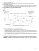
VALVE ORIFICE ADJUSTMENT MANIFOLD PRESSURE REGULATOR ADJUSTMENT INLET PRESSURE Gas Train Illustration REGULATOR ADJUSTMENT VALVE ORIFICE ADJUSTMENT LOW PRESSURE GAS SWITCH DUAL SAFETY SHUTOFF VALVE HIGH GAS PRESSURE SWITCH MANIFOLD PRESSURE Alternate Gas Train Illustration 27 34-53 08/14
13 TROUBLESHOOTING GUIDE Problem Probable Cause Corrective Action Power Supply Check fuse and/or circuit breaker. Check voltage at 120/24V step-down transformer. On-Off Switch Check if On-Off switch is lighted Temperature Control Check that the operating temperature control is set higher than the temperature of the boiler. Flame Safeguard Control Check for bad ground or bad control. Replace if necessary. Remote enable/disable open Enable boiler or place jumper between terminals R1-R2.
14 REPLACEMENT PARTS REPLACEMENT PARTS 29 34-53 08/14
14.
14.2 Control Panel Components (Optional components may not be included) Key No. Part No. 1 101947 2 Description Qty.
14.
14.4 Burner Assembly and Gas Train Components Optional components may not be included) Item 1 2 3 4 5 6 7 8 9 10 11 12 13 14 15 16 17 18 19 20 21 22 23 24 25 26 27 28 29 30 31 32 33 34 35 36 37 50 51 52 53 54 55 56 57 58 59 60 61 62 63 64 65 67 68 69 Qty Burner Assembly Components Part No. Description 1 1 1 1 1 1 1 1 1 4.30 2 1 4.
15 PERIODIC MAINTENANCE Listed below are items that must be checked to ensure safe reliable operations. Maintenance must be performed by a qualified service or maintenance provider. To ensure proper maintenance, the following instructions should be posted near the appliance and maintained in legible condition. Verify proper operation after servicing. WARNING: When servicing the controls, use exact, Factory authorized, replacement parts and label all wires prior to disconnection.
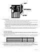
6. The combustion air filter should be replaced every six months. If filter blockage becomes excessive the filter safety switch will not allow the burner to fire. To avoid nuisance shutdown in dirty environments, check and replace filter more frequently. See Filter Replacement Illustration below for removal detail. 7. Inspect low water cutoffs and relief valves for proper operation at every six months, or more often if indicated by inspection. 8.
16 RECOMMENDED MAINTENANCE SCHEDULE 1. 2. 3. 4. 5. Annual Maintenance a. Check all joints and pipe connections for tightness, corrosion or deterioration. b. Check the electronic-ignition system for quick ignition and a proper flame signal. c. Check all safety controls including thermostats for proper operation. d. Check safety shut-off valves for operation and tightness. e. Test flame failure detection system. f. Test high limit and operating temperature controls. g. Conduct a combustion test. h.
NOTES: 37 34-53 08/14
MODEL NUMBER: SERIAL NUMBER: INSTALLATION DATE: Riverside Hydronics, LLC • 990 Haltom Road • Ft. Worth, TX 76117 • 1‐800‐990‐5918 • www.riversidehydronics.