
Instructions / Assembly

TF2246501-RG-00 ENG Page 11 of 16 20160608-Ver.1
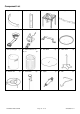
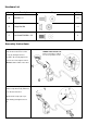
Hardware List
Part
Description
Diagram
Qty.
A
Bolt M6 x 12
12
B
Flange Nut M6
14
C
Crosshead Bolt M6 x 10
4
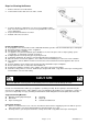
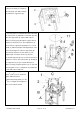
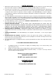
Assembly Instructions:
1. Attach the burner (5) to automatic
shut off valve in the timer control
box (6) by turning the burner
clockwise. Do not fully tighten the
burner to the valve, tighten until 3
threads remain visible on the valve.
2. Attach thermocouple (D) to
thermocouple bracket (E) which has
been fixed to the burner.
Attach thermocouple (D) as per
right drawing and tighten the nut
(Y).
THREE Visible threads left
Proper connection is critical
for correct operation of unit