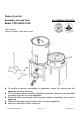
Turkey Fryer Set Assembly, Use and Care For Outdoor Use Only Model: TF21330XX-YY-ZZ Tools required: Phillips screwdriver / Adjustable wrench To installer or person assembling this appliance: Leave this manual with this appliance for future reference. This instruction manual contains important information necessary for the proper assembly and safe use of the appliance. Read and follow all warnings and instructions before assembling and using the appliance.
SAFETY SYMBOLS: The symbols and boxes shown below explain what each heading means. Read and follow all of the messages found throughout the manual. DANGER: Indicates an imminent hazardous situation which if not avoided will result in death or serious injury. WARNING: Indicates a potentially hazardous situation which, if not avoided, could result in death or serious injury. CAUTION: Indicates a potentially hazardous situation, which, if not avoided, may result in minor or moderate injury.
WARNING This Appliance is not intended for commercial use. WARNING 1. 2. 3. 4. 5. 6. 7. 8. 9. 10. 11. 12. 13. 14. 15. 16. 17. Never leave the appliance unattended. Keep children and pets away from the appliance at all times. The use of alcohol, prescription or non-prescription drugs may impair the consumer’s ability to properly assemble or safely operate the appliance. This appliance is for OUTDOOR USE ONLY. DO NOT use in building, garage or any other enclosed area.
foot clearance form walls or rails. Before opening LP tank valve, check the coupling nut for tightness. When appliance is not in use , turn off control knob and LP tank valve. Never move appliance while in operation or still hot. If you notice grease or other hot material dripping from appliance onto valve, hose or regulator, turn off gas supply at once. Determine the cause, correct, clean and inspect valve, hose and regulator before continuing. Perform a leak test.
Do not store LP tanks in an area where children play. LP Tank The LP tank used with your appliance must meet the following requirements: Purchase LP tanks only with these required measurements: 12” (30.5cm) ( diameter) x 18”(45.7cm)(tall) with 20lb. (9kg). Capacity maximum.
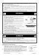
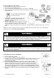
Connecting Regulator to the LP Tank 1. Place LP tank on a secure, level, and stable surface. 2. Turn control knob to the OFF position. 3. Turn LP tank OFF by turning OPD hand wheel clockwise to a full stop. 4. Remove the protective cap from the LP tank valve. Always use dust cap and strap supplied with valve. Do not use a POL transport plug (A) (plastic part with external threads)! It will defeat the safety feature of the valve. 5. Hold regulator, insert nipple (B) into LP tank valve.
Lighting Instructions Do not lean over LP cooker while lighting. 1 Read all instructions before lighting. 2 Turn regulator control valve to OFF position. 3 Fully turn timer control knob clockwise. 4 Fully open LP bottle valve. 5 Light match and place it over burner. PRESS and HOLD push button of safety valve. Slowly turn ON the regulator control valve. DO NOT stand with head or arms over cooker. 6 When burner is lit, still HOLD the push button for 10 seconds and then release.
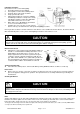
Steps for Cleaning the Burner: 1. Remove orifice/hose from the burner. 2. Look inside the burner tube for nests, webs, or mud. 3. To remove the above obstructions, use an accessory flexible venture brush or bend a small hook on one end of a long flexible wire such as the one in small picture. 4. Inspect and clean the burner if needed. 5. Reattach orifice/hose to burner.
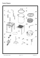
Product Diagram TF2133002-RG-00 ENG Page 9 of 17 20160608-Ver.
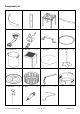
Component List 1. Tip guard 5. Burner 2 pcs 2. Tip guard support 4 pcs 3. Steel Stand 1 pc 4. Timer support 1 pc 6.Timer Control Box 1 pc 7. Pot lid handle 1 pc 8. 30QT Pot Lid 1 pc 9. 30QT Aluminum Pot 1 pc 10. Side table 1pc 11. Heat Shield 13. Fish Pot Lid 1pc 14. Fish basket 1pc 15. Fish basket handle 17. Thermometer 1pc 18” Injector 1pc 19. Lifter TF2133002-RG-00 ENG Page 10 of 17 1pc 1 pc 1 pc 12. T-Star Stand 16. Fish Pot 1pc 1pc 1pc 20160608-Ver.
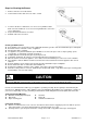
Hardware List Part Description Diagram Qty. A Bolt M6 x 12 12 B Flange Nut M6 14 C Crosshead Bolt M6 x 10 4 O Bolt M5 x 10 4 P Nut M5 4 Q Tooth Washer 4 Assembly Instructions: 1. Attach the burner (5) to automatic shut off valve in the timer control box (6) by turning the burner THREE Visible threads left Proper connection is critical for correct operation of unit clockwise. Do not fully tighten the burner to the valve, tighten until 3 threads remain visible on the valve.
2. Attach thermocouple (D) to thermocouple bracket (E) which has been fixed to the burner. Attach thermocouple (D) as per right drawing and tighten the nut (Y). 3. Insert the burner through the bottom of the stand (3), in between wind shield (F) (side with rectangle lip) and burner support bar (G). 4. Unscrew the pre-assembled nut from the threaded pin of the burner (5).
5. Align the tip guard support (2) th th with 4 and 5 holes to stand and tighten with bolt and nut. Tighten align the tip guard (1) to the st 1 hole of support (2) and tighten it with crosshead bolt and nut. 6. Attach the side table (10) to the stand as shown. 7. Unscrew the pre-assembled bolt and nut from the pot lid handle (7). Attach the pot lid handle to the pot lid (8) by using the bolt and nut. TF2133002-RG-00 ENG Page 13 of 17 20160608-Ver.
8. Attach the fish basket handle (15) to the fish basket (14) by using the bolt, nut and tooth washer. 9. When transporting or storing LP cooker without tank attached, hook regulator onto burner or cooker stand to prevent damage to regulator. Using Your Thermometer Check the thermometer before each use by inserting into a pot of boiling water and ensuring that it registers approximately 212°F +/- 20°F (100°C +/- 10°C).
The following safety measures are recommended when using your fry set. LOCATION MATTERS Select a safe place to fry your turkey. It should be in an open area, outside, and on a cement or brick surface. Place the liquid propane gas tank and fryer so that if any wind blows the heat from the fryer will blow away from the LP gas tank. Never use your fryer in an enclosed area, near a wall or on a wooden deck. Keep a minimum clearance of 10 feet from the sides, front and back of the fryer to any construction.
Light the burner unit and heat the oil to 325°F. Never leave the fryer unattended at any time. Check the oil using a deep fry temperature gauge. If it has reached 325°F, you are ready to start deep frying. Monitor the temperature throughout the frying process to maintain 325°F – never let the oil temperature get hotter than 325°F. If the oil exceeds 400°F or if the oil begins to smoke, immediately turn the burner off.
LIMITED WARRANTY 1. Manufacturer warrants this Product to be free from defects in workmanship and materials for a period of Ninety (90) days from the date of purchase, PROVIDED claims are submitted, in writing, with proof of purchase. 2.