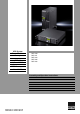
UPS System Power Modular Concept PMC 12 1, 2 and 3kVA 7857.430 7857.431 7857.432 7857.482 7857.
Microsoft Windows is a registered trademark of Microsoft Corporation. Acrobat Reader is a registered trademark of Adobe Systems Incorporated.
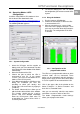
Important Safety Instruction EN Table of Contents 1. IMPORTANT SAFETY INSTRUCTION 3 1.1. 1.2. 1.3. 1.4. 1.5. 1.6. DOCUMENTATION NOTES ........................... 3 RETENTION OF THE DOCUMENTS ................ 3 USED SYMBOLS ......................................... 3 SAFETY INSTRUCTIONS .............................. 3 PROPER USE ............................................ 4 STORAGE INSTRUCTIONS............................ 4 2. PRODUCT INTRODUCTION ..............5 2.1. 2.2. GENERAL CHARACTERISTICS .....
Important Safety Instruction 1. Important Safety Instruction 1.1. Documentation Notes The audience for this guide is the technical specialist familiar with the assembly, installation and operation of the PMC12 UPS-System. You should read this operating guide prior to commissioning and store the guide so it is readily accessible for subsequent use. Rittal cannot accept any liability for damage and operational malfunctions that result from the non observance of this guide. 1.2.
Important Safety Instruction When installed and being used, the batteries will be automatically recharged and kept in top condition. 14. Make sure that the AC Utility outlet is correctly grounded. 15. Please ensure that the input voltage of the UPS matches the utility supply voltage. Use a certified input power cable with the correct plugs and sockets for the appropriate voltage system. 16. Use only genuine or recommended parts and accessories.
Product Introduction 2. Product Introduction the UPS to integrate even in the most difficult of environments with space constraints. 2.1. General Characteristics 1. True online technology continuously supplies your critical device with stable, regulated, transient-free pure sine wave AC Power. 1. 2. 3. 4. 5. 6. 7. 8. 9. High-efficiency 20 kHz PWM sine-wave topology yields an excellent overall performance.
UPS Functional Descriptions EN 3.1.1. Symbols on the LCD Display Panel 3. UPS Functional Descriptions 3.1.
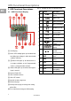
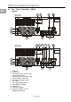
UPS Functional Descriptions 3.2. Rear Panel Description PMC12 EN 230V 1KVA 2KVA 3KVA 1. 2. 3. USB Port RS232 Port Emergency Power Off (EPO) Dry Contact Signal inputs 4. Communication Card Options Slot 5. External Battery Connector 6. AC power connection socket 7. AC Outlets 8. Two programmable outlets 9. Utility Input fuse holder 10. Cooling Fans 11. Output fuse holders 12.
UPS Functional Descriptions EN 3.3. Rear Panel compact Description PMC12 5 4 2KVA 9 6 1 2 3 10 8 7 5 4 12 11 9 3KVA 1 2 3 10 8 1. USB Port 2. RS232 Port 3. Emergency Power Off (EPO) Dry Contact Signal inputs 4. Communication Card Options Slot 5. External Battery Connector 6. AC power connection socket 7. AC Outlets 8. Two programmable outlets 9. Utility Input fuse holder 10. Cooling Fans 11. Output fuse holders 12.
UPS Functional Descriptions 6. 3.4. Operating Modes & UPS Configuration Install the “Rittal PMC12 UPS-Software“ from the enclosed CD or download it from http://www.rimatrix5.com/service_support/downloads.asp. Run the programm „UPSMan Configuration“. The following Window appears: To save the settings press “OK”. To activate the configuration you have to restart the UPSSystem. 3.4.2. Using the Software 1. Run the program „UPSMonitor“ 2. Choose the connection on which the UPS is connected to the PC. 3.
UPS Functional Descriptions 4. EN Turn outlet OFF when battery lower …% - select this option to automatically disable the outlet at the specified remaining battery power capacity(%) during battery mode to shed the less critical loads to prolong battery back-up time for the other more critical loads connected to the UPS. 5. Turn outlet OFF when UPS overload – select this option to automatically disable the outlet during overload condition (bypass mode) to possibly allow the more critical loads 6.
Installation and Operation 4. Installation and Operation 3.5.1. True RS232 Port Descriptions The RS232 interface shall be set as follows: Baud Rate Data Length Stop Bit Parity 2400 bps 8 bits 1 bit None 4.1. Unpacking The Pin Assignments of the true RS232 port are illustrated as follows: 5 4 3 2 1 9 8 7 6 • EN Warning! Read the Safety Instruction guide (page 5 to 6) before installing the UPS! Pin 3: RS232 Rx Pin 2: RS232 Tx Pin 5: Ground Inspect the UPS upon receipt.
Installation and Operation EN 5. This UPS is not designed for outdoor use. 4.3. Set up 4.3.1. Tower Configuration Setup 4.3.2. Power Module + Battery Module Step 1 Relative humidity (non condensation) 30%~90% Note! The recommended temperature range for the batteries is between 20 and 30°C. Is the UPS running permanent in an environment with temperatures over 40°C this will lead to a clear shortened life-time of the batteries. In some cases this can cause damage on the batteries and the ups.
Installation and Operation EN 4.3.3.
Installation and Operation EN 4.4. Operation 4.4.1. Start Up In Normal Mode 1. Make sure the voltage of Utility matches with the input voltage window of the UPS. 2. Connect the UPS to the wall Receptacle of the Utility. Turn on the UPS “ON” switch to (Nr. 2) and (Nr. start up the UPS. LED 5) light up to indicate the Utility and the Bypass are normal. The LCD will illustrate from drawing A to drawing B. drawing D drawing E 6.
Installation and Operation must be completely restarted to get back to Normal Mode. EN drawing M drawing H 4.4.3. Check Measured Values & Figures detected by UPS If you would like to check the measured values drawing N & messages, please use scroll up and scroll down key pads.
Installation and Operation quency Synchronized Window)Ædrawing T (Inverter Output Voltage)Ædrawing U1(UPS Operation Mode)Ædrawing V(Output Voltage Fine Tuning).
Installation and Operation 3. Press scroll up key pad, you may execute special functions. The functions include Buzzer ON (as drawing Q1) or buzzer OFF (as drawing Q2, Alarm silence for UPS warning) and self-test OFF (as drawing Q2). UPS will execute battery test for 10 seconds, if the self-test is successful, it show as drawing W; otherwise, it will show as drawing D & error message at the same time. drawing X. All those changes will be activated only when the UPS is re-turned on.
Installation and Operation (b) Check to see Chapter 6.1 to trouble shoot the problem of the UPS; otherwise, consult your local distributor for service. (c) Press key pad for 5 seconds and buzzer will sound twice. (d) Turn off the Breaker of the Utility Input. (e) The UPS lock problem is solved now. EN 4.4.7. Shut Off 1. Press key pad for about 5 seconds, the Inverter output will be turned off, then the output load is supplied by Bypass loop and the LCD screen shows as Drawing B. 2.
Installation and Operation 4.6. Battery Replacement PMC12 EN Step 4 Step 1 1KVA Step 2 2K/3KVA Note! Was the used battery of the UPS System removed during normal operation this will not immediately be recognized by the PMC12 because after the startup the UPS will check only sporadically (approx. every 60 min.) if there is a battery connected. Step 3 Danger! Do not nip in the ups during a change of batteries.
Installation and Operation EN 4.7. Battery Replacement PMC12 compact Step 4: Step 1: Note! Was the used battery of the UPS System removed during normal operation this will not immediately be recognized by the PMC12 because after the startup the UPS will check only sporadically (approx. every 60 min.) if there is a battery connected. Step 2: Danger! Do not nip in the ups during a change of batteries. Some parts can be under voltage! Warning! The lead acid battery may cause chemical hazard.
UPS Working Principle Paragraph 5.2 ~ 5.7 below provide detailed descriptions of the UPS operating principle. 5. UPS Working Principle 5.1. UPS System Block Diagram 5.2. When Mains is Available When Mains is available, the AC source is rectified to DC, partially fed into the charger to charge battery and partially fed into inverter. The inverter revert the DC to a cleaned and pure AC to supply energy to the load con, LED’s illuminated. nected. The , Fig 5.1 Figure 5.
UPS Working Principle 5.3. When Mains is Absent The working principle of the UPS under Mains absent condition is illustrated as follows: 1. When Mains absent, the UPS will direct the battery energy automatically to the Inverter without delay, and turn off the charger and AC/DC converter. The inverter revert DC to AC to supply energy to the output load con(Nr. 5) nected without interruption. The LED only will be illuminated. 300 250 t in sec. 200 150 100 50 2.
Maintenance Guide 6. Maintenance Guide 5.5.2. Inverter/Internal Over temperature If the UPS experiences internal over-temperature when Utility is normal, it will switch to bypass loop. The UPS will switch back to inverter mode when the over-temperature situation is eliminated. If over temperature occurs when Utility is abnormal, the buzzer will beep conwill light up. The tinuously and the Fault LED UPS will cut off supply to the loads. EN 6.1.
Maintenance Guide EN Situation Check Items UPS fails to provide battery backup or its back up time is shorter than its intended performance. UPS is normal Check if all but no Output to power codes are load properly connected. Solution If the backup time remains nonsatisfactory after 8 hours of charging, please contact your local dealer for battery replacement. If problem persist, consult your local dealer for technical assistance. 1. If any power 1. Do not use The UPS power strip.
Bundle Software Installation 6.2. Error Codes and their Descriptions Descriptions Er05 Battery weak or faulty Er06 Output short-circuited Er07 Er11 Er12 EPO mode UPS over-temperature Inverter overload Er14 Fans out of order Er18 EEPROM's data error Utility Low (<170V) Battery Disconnect Bypass overload Er24 Er28 7.1. 1. Connect the male connector of RS232/USB cable to the UPS communication port. 2. Connect the female connector of the RS232/USB cable to a dedicated RS232 port of the Computer.
Optional Communication Card 8.2. Internal SNMP Adapter EN 8. Optional Communication Card The Simple Network Management Protocol (SNMP) is a worldwide-standardized communication-protocol. It is used to monitor any device in the network via simple control language. The UPS-Management Software also provides its data in this SNMP format with its internal software agent. The operating system you are using must support the SNMP protocol.
Technical Specifications 10.
Technical Specifications EN Harmonic Distortion Efficiency Transient Response(ms) 3% THD(Linear Load) 7% THD(Non-Linear Load) 60ms/5% Waveform Pure Sine wave To AC Mode (Full load) 88% 88% 90% To Battery Mode (Full load) 85% 85% 87% 1KVA 2KVA 3KVA 12V/7,2Ah 12V/7,2Ah 12V/9Ah Numbers of Batteries 3 6 6 Backup Time(100%) >7min. >7min. >5min. Backup Time(80%) >9min. >10min. >9min. Backup Time(60%) >14min. >14min. >12min. Backup Time(40%) >27min. >22min. >19min.
Technical Specifications Protection EN (AC Mode ) <105% continuous >106% ~ 120% for 30 seconds transfer to bypass >121% ~ 150% for 10 seconds transfer to bypass >150% for immediately transfer to bypass Buzzer continuously alarms. (Battery Mode) <105% continuous >106% ~ 120% for 30 seconds shuts down >121% ~ 150% for 10 seconds shuts down >150% for immediately shuts down Buzzer continuously alarms.
Technical Specifications Environmental EN Operation Temperature* 0 - 40 °C Noise Level < 50 dBA Relative Humidity 0 to 90% (Without condensation) Interface Interface Type 1x USB port, 1x RS-232 port, 1x Slot for Communication Card SNMP Power management from SNMP manager and Web browser Compatible platforms Windows 95/98/NT/2000/XP/Vista, Novell NetWare, Linux, etc.
Technical Specifications This side is intentionally empty.
04/11 – A38333 14 IT74 Rittal GmbH & Co. KG · Postfach 1662 · D-35726 Herborn Telefon +49(0)2772 505-0 · Telefax +49(0)2772 505-2319 · eMail: info@rittal.de · www.rittal.