
Owner`s manual


6 Series OUTPOST
®
Wireless Callbox Installation Instructions
Have questions? Call 800-USA-1-USA (800-872-1872) or visit our website at www.ritron.com 6
C
ALLBOX
C
ONTROLS AND
C
ONNECTORS
...............................................
Antenna Connector
The antenna radiates radio signals. Before using the
OUTPOST
®
Callbox, make sure the antenna is securely
fastened into the 50Ω BNC antenna connector. If the
OUTPOST
®
is to be used outdoors, see page 8 for instructions
on properly sealing the antenna connector.
RF Mating Connectors
An internal cable from the antenna connector is terminated into
an SMB style connector for connection to the radio circuit
board.
Captive Plastic Case Screws
A captive plastic case screw is located in each corner of the
case front. These 4 screws are used to secure the case front
containing the radio, to the case back that contains the
batteries.
Charge Jumper
The charge jumper can be set to trickle charge re-chargeable
backup batteries.
Sensor Turn-On Jumper
The Sensor Turn-On jumper can be set to turn-on the radio
whenever the Sensor Input is pulled low.
Input/Output Connector
The 6-pin, polarized connector is used to connect external
input/output devices. This allows connection of an external +12
VDC input, an external DC level sensor input, and a 1A contact
switch closure output.
Speaker Connector
The internal speaker is connected to the radio printed circuit
board with a polarized connector.
On/PTT Connector
The On/PTT switch is connected to the radio printed circuit
board with a polarized connector.
Pre-Drilled Mounting Holes
Mounting holes located in the 4 corners of the case back are
pre-drilled for mounting to a plate, wall or post. Once mounted,
the case front is secured to the case back through these same
threaded holes.
RJ-11 Program Cable Connector
An RJ11 style connector is used to connect the cable from the
PC programmer to the radio.
Program Button
A small, momentary pushbutton is used for field programming
the OUTPOST
®
Callbox.
Program Display
A single digit LED display is used during field programming of
the radio.
Battery Holder
The battery holder inside the case back is used for the
installation of 6 D-cell alkaline batteries. Refer to the diagram
below, or the labels beneath the cells, for correct installation of
the batteries.
Battery Mating Connectors
Polarized, 2-pin mating connectors are used to connect the
batteries to the radio circuit board.
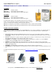
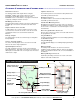
RF Mating Connectors
50
Ω
BNC Antenna Connecto
r
Pro
g
ram Button
Pro
g
ram Dis
p
la
y
Battery Mating
Connectors
Battery Holder with
D-Cell Batteries Installed
Pre-Drilled Mounting
Holes
(
4 Corners
)
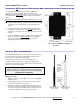
FIG-3: Callbox Assembly, Controls and Connectors
S
p
eaker Connecto
r
Input
/
Output
Co
nn
e
c
tor
Captive Plastic Case
Screws
(
4 Co
r
ners
)
RJ-11 Pro
g
ram Cable Connecto
r
Char
g
e Jum
p
er
On/PTT Connecto
r
Sensor Turn-On
Jum
p
e
r