
Owner`s manual

6 Series OUTPOST
®
Wireless Callbox GateGuard
®
Application
Have questions? Call 800-USA-1-USA (800-872-1872) or visit our website at www.ritron.com 23
F
IG
:
6
XT
C
ALLBOX
A
SSEMBLY
.............................................................
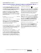
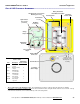
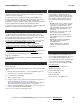
• Do not remove the foam Antenna Locator.
The foam Antenna Locator is used to position the antenna for optimum
performance. The antenna should be routed in the slot on Antenna Locator, along the inside of the XT case as shown. The tip
of the antenna should not come in contact with any of the connecting cables.
Captive Plastic
Case Screws
(4 Corners)
RF Mating
Connectors
Battery Mating
Connectors
On/PTT Switch
Front Plate
(Bottom Edge)
Threaded Inserts for Front Plate
Mounting (4 Corners)
Internal Antenna
Battery Holder with
D-Cell Batteries Installed
6-Conductor
Interface Cable
Charge
Jumpe
r
Input/Output
Connecto
r
Sensor Turn-On
Jumper
Cables must be
routed to the side of
internal plastic case
assembly.
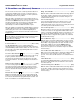
Table 7: XT Callbox 6-Conductor
Interface Cable
Input/Output
Wire Description Connector Pin #
Red External 12 VDC 6
“+” input
Black External 12 VDC 5
“-“ input
Blue Switch Output 4
“+” connection
Green Switch Output 3
“-“ connection
White Sensor Input 2
“+” connection
Brown Sensor Input 1
“-“ ground
Foam Antenna
Locator