
Owner`s manual

6 Series OUTPOST
®
Wireless Callbox GateGuard
®
Application
Have questions? Call 800-USA-1-USA (800-872-1872) or visit our website at www.ritron.com 22
C
ONFIGURING THE
C
ALLBOX FOR A
G
ATE
G
UARD
®
A
PPLICATION
...............
The XT OUTPOST
®
can be mounted to virtually any surface with
four (4) ¼” panhead screws. Choose a type of screw thread and
screw length which will hold firmly in the surface to which the unit
will be mounted.
MOUNTING the XT OUTPOST
®
: ( Refer to FIG-6)
1. Remove the front faceplate from the XT Callbox. The faceplate
is secured to the case with 4 vandal-resistant buttonhead, Torx
screws. Use the T-25 Torx bit included with the radio to remove
these screws.
2. Remove the “Mounting Bracket” kit secured to the inside of the
XT Callbox case.
3.
4. Remove the 4 flathead screws securing the internal mounting
plate and remove entire internal case assembly. The front
faceplate will be attached to the internal case assembly,
handle with care.
5. Carefully drill the hole in the XT Callbox case required for your
external hook-up cable installation.
6. Install the 4 mounting brackets to the back of the XT Callbox
case shown in FIG-4 on page 7. The mounting brackets can
be installed vertically, as shown, or horizontally.
7. CONNECTING THE SWITCH OUTPUTS TO AN EXTERNAL
DEVICE
a. Thread your external hookup cable from the external
device you wish to control through the hole with
approximately 6 inches of cable inside the XT case.
b. Your external cable will be connected to the XT Callbox
6-conductor interface cable with wirenuts, dress your
external wires accordingly (Refer to Table 7 on page 23).
c. With your selected hardware, secure and seal the conduit
to ensure moisture and vandal resistant functions to the
XT Callbox case.
• Consult the manufacturer of the external device you are
attempting to control for the recommended wire gauge.
• Confirm that your application will NOT exceed the
maximum rating of the on-board relay of 120 VAC @ 1
amp.
• Make sure all power to the equipment is turned OFF or
disconnected.
CAUTION: The interface cable and wirenuts should be
positioned on the right
side of the case, opposite the antenna
(See FIG-6 on page 23)
8. Position the XT Callbox case in the chosen installation location
and secure it in place with four screws through the mounting
brackets.
9. If programming is required, loosen the (4) captive screws in
the front corners of the internal Callbox case and separate the
case front from the case back. These screws are captive to
the housing; to prevent damaging them, DO NOT remove the
screws from the housing.
10. Program the radio, if required. Refer to the programming
section of this manual for details. To program the radio you
must first apply +12 VDC external power, or alkaline batteries.
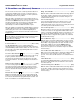
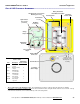
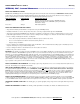
11. If rechargeable NiCd batteries are used for battery backup the
“Charge Jumper” must be placed into the “charge” position as
shown below.
! ! CAUTION ! !
If rechargeable batteries are NOT used for battery backup, be
sure the “Charge Jumper” is NOT in the “charge position.
Charging alkaline batteries will damage the cells and reduce
battery life!
12. Fasten the internal case front to the case back with the four (4)
captive screws. Do not over-tighten the plastic screws to prevent
damage.
13. Secure the internal case assembly to the XT Callbox with the
4 flathead screws through the internal mounting plate. Refer to
FIG-6 for correct orientation and location of the antenna and
cables. The front faceplate is attached to the internal case
assembly, handle with care.
14. Re-fasten the front faceplate to the radio with the 4 buttonhead
Torx screws.
Be sure both the interface cable and the front-panel On/PTT
switch cable are routed to the side of the internal plastic case
assembly, away from the antenna. The cables cannot lay
across the face of the internal plastic case, they must be
alongside.
Charge Jumper in
Charge
position
!
!
Due to the wide variety of installation possibilities,
RITRON does not provide the cables or hardware
required to bring external connections into the XT
Callbox.
• When selecting your cable hardware be sure it
will adequately seal the cable to the case.
• Carefully study the internal construction of the
XT Callbox and determine the location on the
outside case where the external supply and
GateGuard
®
hook-up will be brought in.
• Consider clearance with your desired hardware.