
User's Manual


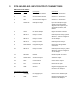


3 DTX-165-RR-SIG INPUT/OUTPUT CONNECTORS
DB-15 Connector Pinout
Pin Number Name Description Comments
1 CS0 Channel Select low bit Channel 1 – 8 selection.
2 CS1 Channel Select mid bit Channel 1 – 8 selection.
3 CS2 Channel Select high bit Channel 1 – 8 selection.
4 AUDIO IN Microphone Input Input for microphone type
signals to be transmitted.
Signals at this input are pre-
emphasized, limited, and
filtered.
5 HI/LO RF Power Output High/Low Power selection.
6 RELAY 1 Relay 1 Contact N/O Output for Relay1, paired
with Pin 7. Can be configured
7 RELAY 1 Relay 1 Contact as N/C Output.
8 RELAY 2 Relay 2 Contact N/O Output for Relay 2.
9 PGN IN/OUT Programming I/O External PC Programmer
connection.
10. RELAY 2 Relay 2 Contact N/O Output for Relay 2, paired
with Pin 8. Can be configured
as N/C Output.
11. RX MON Monitor Breaks squelch in receive.
12. AUDIO OUT Audio PA Output Audio PA output.
13. DCD Carrier Detect Carrier detect output.
14. PTT Push to Talk External PTT input.
15. GND Ground Negative supply point and
reference for all inputs.
2-Pin Molex Connector
1 +Vsupply DC Supply Input External +10–16VDC Input.
2 GND Ground Negative supply point and
reference for all inputs.