
User's Manual

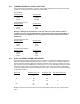


TX Pre-emphasis- Allows for the signal path from AUDIO IN input to be either pre-emphasized or
flat. Most applications the AUX IN input is used work best with a pre-emphasized response.
Factory default is pre-emphasized.
RX De-emphasis- Allows for the signal path from the discriminator to the AUDIO OUT to be either
de-emphasized or flat. Most applications the AUX OUT output is used work best with a de-
emphasized response. Factory default is for a de-emphasized response.
Busy Channel Lockout- Prevents the transmitter from activating when the carrier detect output is
true. Used to prevent interference on a channel where activity already exists. Not normally
enabled in half duplex operation since the transmit and receive channels are not on the same
frequency. Factory default is for this function to be off.
Squelch Enable- Allows the receive audio path to be muted when the carrier detect output is
false. It is used to prevent the output of noise from the audio output when no signal is present.
Due to the finite squelch attack time, some high-speed modems work best with unsquelched
audio. The factory default is for this function to be set for never mute.
DCD Output Logic Level- Allows the setting of the polarity of the DCD (Data Carrier Detect)
output. Active high means that the true state is a logic high while active low means that the true
state is logic low. Normal setting is active high. The factory default is active high.
Monitor Polarity- The monitor input is used to override the action of the receiver squelch (mute)
when squelch is active. This function sets the polarity, active low or active high, of this input.
When active, squelch is disabled, even is enable via the Squelch Enable setting above.
PTT Input Logic Level- Sets the polarity of the PTT input. Normally set for active low i.e.
transmitter is activated when this input is at the logic low state. Due to the internal pull-up
resistor, setting this to active high will cause activation of the transmitter when the PTT
input is left unconnected. The factory default is active low.
Green LED- Sets the operation of the green LED on the front of the radio. The choices are:
a. Off-The green LED is never on.
b. Power ON-The green LED is on whenever the radio is powered up.’
c. Carrier Detect-The green LED is on whenever a carrier is detected that is above the
programmed carrier detect on threshold.
d. RX Synthesizer Lock-The green LED is on whenever the frequency synthesizer is locked while
in receive mode. This is the factory default setting.
Red LED- Sets the operation of the red LED on the front of the radio. The choices are:
a. Off-The red LED is never on.
b. RX-The red LED is on whenever the radio is actually transmitting. This is the factory default
setting.
TX Timeout Timer- Allows for limits on the maximum time the transmitter may be continuously
keyed. When set, the maximum limit is set in the box. To prevent overheating and possible
damage to the unit, this is normally set on with a time of 60 seconds or less. See section 5.4 for
limits on maximum key-down times. The factory default is 60 seconds.
DTMF- The DTMF decoder codes for Relay1 and Relay2 are programmable to a maximum of 12
characters. The options are:
a. Close Relay1- DTMF code to cause the contacts of Relay1 to close.
b. Open Relay1- DTMF code to cause the contacts of Relay1 to open.
c. Momentary Relay1- DTMF code to cause the contacts of Relay1 to momentarily close for the
programmed Rly1 Duration.
d. Close Relay2- DTMF code to cause the contacts of Relay2 to close.
e. Open Relay2- DTMF code to cause the contacts of Relay2 to open.
f. Momentary Relay2- DTMF code to cause the contacts of Relay2 to momentarily close for the
programmed Rly2 Duration.