
User's Manual


4 ACCESSORIES
Note: Programming kits are for use by authorized service/maintenance personnel only.
The Programming Kit for the DTX-165-RR-SIG radios (via compatible computer) is model DTXT-
PCPK. It includes:
1) Programming Software CD, DTXT-PCPS.
2) (1) 25 pin PC to 6 pin modular adapter cable with built-in interface circuitry, 9/RTC-PAS.
3) 1 modular adapter to DB-15 connector cable with power cable, DTXP-PAC.
4) 9-Pin to 25-Pin Adapter, 2147C001.
Factory programming of channels and features is also optional. Contact the factory for details.
5 OPERATION
5.1 CHANNEL SELECTION
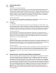
The DTX-165-RR-SIG module supports eight channels. The desired channel is chosen via pins
1, 2, and 3 of the 15 pin connector as shown:
Channel CS2 CS1 CS0 0 = Logic low(0 to 0.3VDC)
1 0 0 0 1 = Logic high(3.5 to 5.0VDC)
2 0 0 1
3 0 1 0
4 0 1 1
5 1 0 0
6 1 0 1
7 1 1 0
8 1 1 1
A logic low is a voltage level below 0.3 volt while a logic high is a voltage level above 3.5 volts.
These three pins have an internal 10 k pull-up resistor to + 5 volts. Therefore, any pin left
unconnected will assume a logic high state. DO NOT apply voltages outside the range of 0 to +5
volts to these pins. Note: When the Ritron programming cable is connected, these pins are not
connected and thus, assume a logic high state. Therefore, the radio will be on channel 8 when
the Ritron programming cable is connected.
A change in the channel selection in receive will cause the receiver to operate on the new
channel. In transmit, however, the channel selection is only checked upon a push-to-talk
activation. Changes in channel during transmit will not change the transmitter operating channel
of the unit until the unit is cycled from transmit to receive and back to transmit.
5.2 POWER SUPPLY VOLTAGE
The 2-pin Molex connector is the supply voltage input to the unit. One should be absolutely sure
of the proper voltage and current requirements before applying power.
The DTX-165-RR-SIG unit uses 12.5 volt RF power modules. The supply voltage can be at any
voltage between 11 and 16 volts. Since the module is powered directly from this voltage, the
supply should be “clean” and, preferably, regulated. The output power will vary slightly with
supply voltage. Switching power supplies can be used, but care must be taken that the output
waveform is low noise. Also, the module antenna should never be placed near an unshielded
switching power supply.