RITRON, INC.
TABLE OF CONTENTS I DTX MODULES 1 INTRODUCTION 1.1 GENERAL 2 1.2 MODEL IDENTIFICATION 1.3 FCC REGULATIONS MODELS DTX-165 AND DTX-265 SPECIFICATIONS 2.1 GENERAL 2.2 TRANSMITTER 2.3 RECEIVER 3 DTX-165-RR-SIG INPUT/OUTPUT CONNECTOR 4 ACCESSORIES 5 OPERATION 5.1 CHANNEL SELECTION 6 5.2 POWER SUPPLY VOLTAGE 5.3 CURRENT DRAIN VS. SUPPLY VOLTAGE 5.4 DUTY CYCLE/KEY-DOWN LIMITATIONS 5.5 OPERATING MODES 5.6 RECEIVER SELF-QUIETING SPUR (BIRDIE) FREQUENCIES PROGRAMMING 6.
9 HARDWARE OPTIONS 9.1 CONTROL/LOADER BOARD OPTIONS 9.2 10 RF BOARD OPTIONS ALIGNMENT 10.1 REQUIRED TEST EQUIPMENT 10.
I DTX-165-RR-SIG MODULES 1 INTRODUCTION 1.1 GENERAL The RITRON DTX-165-RR-SIG module is a programmable 2-way radios, which operates in the VHF professional FM communications band. Each of eight channels can be programmed to contain a unique set of operating frequencies. The DTX-165-RR-SIG module is made up of two PC boards, an RF board and a control/loader board.
RF energy, however, should not be confused with these other forms of electromagnetic energy, which when used improperly can cause biological damage. Very high levels of x-rays, for example, can damage tissues and genetic material. Experts in science, engineering, medicine, health and industry work with organizations to develop standards for exposure to RF energy. These standards provide recommended levels of RF exposure for both workers and the general public.
Instructions: • Transmit no more than the rated duty factor of 50% of the time. To transmit (talk or send data), assert the PTT input pin. To receive calls, un-assert the PTT input. Transmitting 50% of the time, or less, is important because this radio generates measurable RF energy exposure only when transmitting (in terms of measuring for standards compliance).
2 SPECIFICATIONS 2.1 GENERAL 2.2 FCC/IC Identifier FCC IC AIERIT42-165 1084A-RIT42165 FCC Rule Parts 90 Industry Canada Rule Parts RSS-119 Frequency Range 136-174 MHz Number of Channels 8 Transmit/Receive Spacing Up to the span of the sub-band Mode of Operation Simplex or Half Duplex Frequency Control PLL Synthesizer Channel Increment (Synthesizer step size) 2.5 kHz Emissions Bandwidth 16 kHz Frequency Stability -30 C to +50 C -40 C to +60 C +/-1.0 ppm +/-1.
Transmitter Attack Time: 10 ms max. Spurious and Harmonics -20 dBm max. FM Hum and Noise (12.5kHz) 45 dB min. Group Delay Variation (Within Frequency Response) 5 us max. Current Drain Depends upon supply voltage (see chart elsewhere in manual). AUDIO IN adjustment range (60% rated dev.) w pre-emphasis (@ 1 kHz) w/o pre-emphasis (flat) 2.3 200 to 1000 mV rms 40 to 300 mV rms RECEIVER Operating Bandwidth Up to span of the sub-band Sensitivity (12 dB SINAD @ 1 kHz w de-emphasis) 0.25 uV (-119.
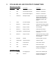
3 DTX-165-RR-SIG INPUT/OUTPUT CONNECTORS DB-15 Connector Pinout Pin Number Name Description Comments 1 CS0 Channel Select low bit Channel 1 – 8 selection. 2 CS1 Channel Select mid bit Channel 1 – 8 selection. 3 CS2 Channel Select high bit Channel 1 – 8 selection. 4 AUDIO IN Microphone Input Input for microphone type signals to be transmitted. Signals at this input are preemphasized, limited, and filtered. 5 HI/LO RF Power Output High/Low Power selection.
DB-15 Pinout Description Pin Number Description 1 CS0- Least significant bit of the channel select lines. Active high 5 volt TTL/CMOS level. Internal 10 k pull-up to +5 volts. 2 CS1- Mid bit of the channel select lines. Active high 5 volt TTL/CMOS level. Internal 10 k pull-up to +5 volts. 3 CS2- Most significant bit of the channel select lines. Active high 5 volt TTL/CMOS level. Internal 10 k pull-up to +5 volts.
4 ACCESSORIES Note: Programming kits are for use by authorized service/maintenance personnel only. The Programming Kit for the DTX-165-RR-SIG radios (via compatible computer) is model DTXTPCPK. It includes: 1) Programming Software CD, DTXT-PCPS. 2) (1) 25 pin PC to 6 pin modular adapter cable with built-in interface circuitry, 9/RTC-PAS. 3) 1 modular adapter to DB-15 connector cable with power cable, DTXP-PAC. 4) 9-Pin to 25-Pin Adapter, 2147C001.
5.3 CURRENT DRAIN VS. SUPPLY VOLTAGE The current drain of the module is a function of the supply voltage and the RF output in transmit. Typical current drain values are shown in the table below: Receive Mode Supply Voltage 11.0 V 12.5 V 16.0 V Current Drain 193 mA 193 mA 193 mA Transmit Mode (5 watt) Supply Voltage 11.0 V 12.5 V 16.0 V Current Drain 2.2 A 2.3 A 2.
5.5 OPERATING MODES 5.5.1 RECEIVE Carrier Detect and Squelch Operation The DTX-165-RR-SIG is a transceiver; i.e. it can receive and transmit, although not at the same time. A carrier detect system exists within the unit to detect the presence of a carrier which controls the logic state of the DCD (data carrier detect) output. The RF levels at which this output changes state are programmable.
6 PROGRAMMING To program the DTX-165-RR-SIG Module, the RITRON PC Programming Kit, DTXT-PCPK, must be used. 6.1 PC PROGRAMMING KIT The user should install the programming software on the host computer. The RITRON adapter cables connect the radio to a computer’s serial communications port. Once the cables are hooked up, the user runs the programmer software. This program transfers data between radio and computer memory. 6.1.
6.5 PROGRAMMER MENUS The DTXT-PCPS Programmer has six menus or pages, selectable via tabs at the top of each page, which are always visible. These pages are: 1. Frequency-Used to program the channel frequencies of the radio. 2. Settings 1-Used to set programmable features/functions of the radio. 3. Settings 2-Used to set adjustable settings of the radio. 4. Alignment-Used to align and set the internal digital potentiometers in the radio.
TX Pre-emphasis- Allows for the signal path from AUDIO IN input to be either pre-emphasized or flat. Most applications the AUX IN input is used work best with a pre-emphasized response. Factory default is pre-emphasized. RX De-emphasis- Allows for the signal path from the discriminator to the AUDIO OUT to be either de-emphasized or flat. Most applications the AUX OUT output is used work best with a deemphasized response. Factory default is for a de-emphasized response.
The Settings 2 page allows for programming various adjustments of the radio. These are detailed below: Audio Input (TX) Gain- This input allows adjustment of the signal level to be applied to the modulation limiter and filter circuits from the AUDIO IN input. At the maximum gain setting the AUDIO IN signal can achieve 60% modulation with 4 mv rms in the low gain position and 0.5 mv in the high gain position. The setting can vary from 0 for muted input to 32 for maximum gain.
6.5.4 SUMMARY The summary page summarizes the information shown on the other three pages and, in addition, includes the model and serial number of the unit. 6.5.5 RESTORE EEPROM This selection is used to load a previously saved radio configuration file to the radio connected to the programmer. This is of benefit when a number of radios are to set to the same frequencies and with the same switch settings.
II MAINTENANCE 7 IMPORTANT MAINTENANCE INFORMATION Surface Mount Repair: RITRON surface mount products require special equipment and servicing techniques. Improper servicing techniques can cause permanent damage to the printed circuit board and/or components, which is not covered by RITRON’s warranty. If you are not completely familiar with surface mount component repair techniques, RITRON recommends that you defer maintenance to qualified service personnel.
8 THEORY OF OPERATION 8.1 DTX-165 RF BOARD 8.1.1 RECEIVER RF amplifier and Bandpass Filters The incoming RF signal from the antenna connector passes backwards through the transmitter harmonic filter and to a diode switch. The diode switch, CR101, CR103, and CR201 route the RF signal to a lumped-element bandpass filter and then an amplifier Q101. The amplifier is followed by another lumped-element filter.
8.1.2 Transmitter PA Driver Stages The output of the VCO buffer drives Q203 to provide a drive level to the RF PA device of about +17 dBm. The supply voltage to this stage is switched on in transmit by Q201 and Q202. PA Module, Lowpass Filter, and T/R Switch When driven by +17 dBm, the PA module, U201, is capable of producing full rated power at the antenna connector. Pin 2 of the module is used for power control.
8.2 CONTROL/LOADER BOARD The control/loader board is responsible for controlling the operation of the RF board and for processing the audio input and output signals to and from the RF board and to and from the DB15 Connector, J301. Audio Chain The audio processing, both transmit and receive, is handled by the audio processing IC, U302 and the microcontroller U301. These devices handle pre-emphasis, modulation limiting, and lowpass filtering on transmit as well as de-emphasis and filtering on receive.
10 ALIGNMENT Warning: Alignment must only be performed by qualified and trained service personnel. The DTX-165-RR-SIG module is aligned at the factory before shipment and should need no further adjustment. It is possible that the gain settings for the audio input and output signal paths may need optimized. The frequency trim, deviation, and balance should not need adjustment. The procedure for performing all of the alignment steps is detailed below.
A channel with a receive frequency programmed into it should be selected. The correct local oscillator will be displayed on the programmer channel box. The frequency on the counter should be observed and the RX Frequency Trim value adjusted for least error. Because of the very low local oscillator level at the antenna terminals, the frequency counter may not be able to read the frequency.
10.2.6 DEVIATION AND BALANCE The deviation adjustments are used to set the maximum limiting deviation of the transmitter. This must be set properly to ensure that the unit will meet the regulatory spurious emissions requirements, in particular, occupied bandwidth. The balance adjustment is used to ensure a proper relationship between the modulating signal to the reference and to the VCO. If the ratio i.e.