
User's Manual

3 DTXM I/O CONNECTOR AND INDICATORS
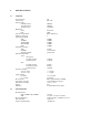
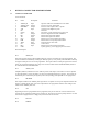
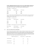
3.1 15-PIN I/O CONNECTOR
Connector Pinout
Pin Name Description Comments
1 AUDIO_IN Input Input for Audio to be transmitted in Voice mode
2 AUDIO_OUT Output Line level receiver audio output
3 SPEAKER Output Receiver audio output to drive a speaker
4 A/B Input Channel 1/2 or High/Low power
5 NC Not Used
6 Supply Input DC Power + input connects here to power unit
7 NC Output Receiver Alignment-Do NOT CONNECT
8 RD Output RS-232 data output from modem
9 TD Input RS-232 data input to the modem
10 CTS Output RS-232 clear to send output from modem
11 DSR Output RS-232 data set ready output from modem
12 TEST Input Used for PTT in voice mode
13 CD Output Carrier detect
14 RTS Input RS-232 request to send input to modem
15 GND System ground, - power supply input connects here
Pinout Description
Pin 1 AUDIO_IN
This is the input for signals to be transmitted when the unit to be operated in the voice/analog mode. The
actual transmission is initiated by asserting the TEST pin (pin 12). The polarity and modulation sensitivity
for signals at this pin can be set via the programmer. The input resistance at this pin is greater than 10 k
and is AC coupled. Note that this pin is only active on the 12.5 kHz channel bandwidth models, NOT on
the 6.25 kHz channel bandwidth models.
Pin 2 AUDIO_OUT
Amplified, buffered, and filtered receiver audio is present at this output. The audio level can be adjusted
via the programmer as well as the choice of a flat vs de-emphasized frequency response. The presence of
audio at this pin is controlled by the squelch (carrier detect) settings, also adjustable via the programmer.
Pin 3 SPEAKER
This output is similar to the AUDIO_OUT signal above except that it is always de-emphasized and is able
to drive an 8-ohm speaker load. The level is adjustable via the programmer with the same setting as that
which sets the AUDIO_OUT level.
Pin 4 A/B
Depending on how it is programmed via the programmer, this pin can either be a channel A/channel B
selection pin or a high/low transmit power selection pin. This pin has an internal pullup resistor to +5 volts
and assumes a high (channel A or high power) state when left unconnected.
Pin 5 Not Used
Pin 6 SUPPLY