RITRON, INC.
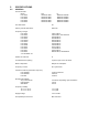
TABLE OF CONTENTS I DTX MODULES 1 INTRODUCTION 1.1 GENERAL 1.2 MODEL IDENTIFICATION 1.3 FCC REGULATIONS 2 MODELS DTX-965 SPECIFICATIONS 2.1 GENERAL 2.2 TRANSMITTER 2.3 RECEIVER 3 DTX-965 INPUT/OUTPUT CONNECTOR 4 ACCESSORIES 5 OPERATION 5.1 CHANNEL SELECTION 5.2 POWER SUPPLY VOLTAGE 5.3 DUTY CYCLE/KEY-DOWN LIMITATIONS 5.4 OPERATING MODES 5.5 RNET COMPATIBILITY MODE 6 PROGRAMMING 6.1 PC PROGRAMMING KIT 6.2 LOADING THE PROGRAMMING SOFTWARE 6.3 COMPUTER SOFTWARE COPYRIGHTS 6.
1 INTRODUCTION 1.1 GENERAL The RITRON High Power DTX Plus modules are programmable 2-way radios, which operate either in the VHF or UHF professional FM communications bands as well as a number of other bands in the 220 MHz, 350 MHz, and 900 MHz region. Each of eight channels can be programmed to contain a unique set of operating frequencies. The High Power DTX Plus module is made up of two PC boards, an RF board and a control/loader board.
The part number system for a stand-alone RF board/Heat Sink assembly is the same as that for a module except that “F” designator (regulator option) does not exist and a “D” is appended at the end. 1.3 FCC REGULATIONS 1.3.1 LICENSING For those frequency bands governed by FCC rules, the FCC requires that the radio owner obtain a station license for his radio before using the equipment to transmit, but does not require an operating license or permit.
Federal Communications Commission Regulations: The FCC rules require manufacturers to comply with the FCC RF energy exposure limits for mobile 2-way radios before they can be marketed in the U.S. When 2-way radios are used as a consequence of employment, the FCC requires users to be fully aware of and able to control their exposure to meet occupational requirements. Exposure awareness can be facilitated by the use of a label directing users to specific user awareness information.
NOTE - Table 1 lists the recommended minimum lateral distance for bystanders in an uncontrolled environment from transmitting types of antennas (i.e., monopoles over a ground plane, or dipoles) at several different ranges of rated radio power for mobile radios installed on a vehicle. For mobile applications, this transmitter is restricted for use only in a locomotive, and the antenna must be mounted on the metal roof of the locomotive. Table 1.
2 SPECIFICATIONS 2.
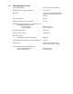
Supply Input Connector 2-Pin Molex Data Interface 15 pin subminiature D type Operating Temperature -30 to +60 C Maximum Dimensions (L x W x H) 6.6” x 5.0” x 2.4” including connectors Weight 35 oz.
2.2 TRANSMITTER( DTX-965) Operating Bandwidth Up to the span of the sub-band RF Output Power (internally adjustable) 5 to 30 watts Duty Cycle 5 to 100 % depending upon ambient temperature(see chart elsewhere in manual) RF Load Impedance 50 ohms Modulation Distortion (per TIA/EIA 603) 5 % max.
2.3 RECEIVER (DTX-965) Operating Bandwidth Up to span of the sub-band Sensitivity (12 dB SINAD @ 1 kHz w de-emphasis) 0.25 uV (-119.0 dBm) typical RF Input Impedance 50 ohms nominal Adjacent Channel Selectivity +/- 12.5 kHz w narrow IF 60 dB min. Spurious and Image Rejection IF/2 Image & other 100 dB min. 70 dB min. Intermodulation Rejection 80 dB min. FM Hum and Noise Very narrowband (5/6.25/7.5 kHz) operation Narrowband (12.5/15 kHz) operation Wideband (25/30 kHz) operation 40 dB min.
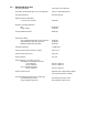
3 DTX INPUT/OUTPUT CONNECTORS DB-15 Connector Pinout Pin Number Name Description 1 CS0 Channel Select low bit 2 CS1 Channel Select mid bit 3 CS2 Channel Select high bit 4 MIC IN Microphone Input 5 CSN High/Low Power or Channel 1/2 (in RNet Mode) 6 NC No Connection 7 AUX IN Auxiliary Input Wideband input for data. 8 AUX OUT Auxiliary Output Wideband output for data. 9 PGN IN/OUT Programming I/O External programmer connects here. 10.
3 CS2-Most significant bit of the channel select lines. Active high 5 volt TTL/CMOS level. Internal 10 k pull-up to +5 volts. Channel 1 2 3 4 5 6 7 8 0 0 0 0 1 1 1 1 CS2 CS1 0 0 1 1 0 0 1 1 0 1 0 1 0 1 0 1 CS0 0 = Logic low 1 = Logic high Note: Due to the internal pull-up resistors, the unit defaults to channel 8 if the channel pins are left open (unconnected). Channel 8 would be the nominal channel when the Ritron programmer is connected. 4 MIC IN-Microphone input.
4 12 AUDIO OUT-This is the output of the audio power amplifier. This output can drive up to 100 milliwatts into an 8 ohm load. The output level can be controlled by programming. De-emphasis can be applied to this output, but not independently of the AUX OUT output. Note that this output level varies with the adjustment via the programmer of the AUX OUT level. Thus, the AUX OUT level should be set first before adjusting the AUDIO OUT level. 13 DCD-Carrier detect output.
5 OPERATION 5.1 CHANNEL SELECTION The DTX module supports eight channels. The desired channel is chosen via pins 1, 2, and 3 of the 15 pin connector as shown: Channel Pin 3 (CS2) Pin 2 (CS1) Pin 1(CS0) 1 2 3 4 5 6 7 8 0 0 0 0 1 1 1 1 0 0 1 1 0 0 1 1 0 1 0 1 0 1 0 1 0 = Logic low (0 to 0.3 VDC) 1 = Logic high (3.5 to 5.0 VDC or left unconnected) A logic low is a voltage level below 1 volt while a logic high is a voltage level above 3.5 volts.
Transmit Mode – 5 watt output power Supply Voltage Internal Regulator 11.0 V 12.5 V 16.0 V Yes Yes Yes Current Drain 3.4 A 3.9 A 4.8 A Warning: Although the output power can be set as low as 5 watts, and the module is certified as low as 5 watt, operation below 5 watts output power is not recommended. At low power levels, the output power can vary by 50% or more with variations in ambient temperature. Transmit Mode – 15 watt output power Supply Voltage Internal Regulator 11.0 V 12.5 V 16.
5.5 OPERATING MODES 5.5.1 RECEIVE Carrier Detect and Squelch Operation The DTX is a transceiver; i.e. it can receive and transmit, although not at the same time. A carrier detect system exists within the unit to detect the presence of a carrier which controls the logic state of the DCD (data carrier detect) output. The RF levels at which this output changes state are programmable.
Specialized Modem Operation Modems designed to achieve the highest data rates possible in a radio channel may require a direct DC connection to the modulation path and the removal of the limiter-filter. In order to receive FCC Certification, the DTX module must either be tested and approved with a specific modem connected to the transmitter, or a modulation limiter and limiter-filter must always be present in the transmit modulator audio path with the modulation inputs AC coupled.
6 PROGRAMMING To program DTX Module, the RITRON PC Programming Kit, DTXP2-PCPK-1, must be used. 6.1 PC PROGRAMMING KIT The user should install the programming software on the host computer. The RITRON adapter cables connect the radio to a computer’s serial communications port. Once the cables are hooked up, the user runs the programmer software. This program transfers data between radio and computer memory. 6.1.
6.5 PROGRAMMER MENUS The DTX Programmer has five menus or pages, selectable via tabs at the top of each page, which are always visible. These pages are: 1. Frequency-Used to program the channel frequencies of the radio. 2. Settings-Used to set programmable features/functions of the radio. 3. Alignment-Used to align and set the internal digital potentiometers in the radio. Information on the use of this page is found in the Maintenance section of the manual. 4.
TX Pre-emphasis- Allows for the signal path from AUX IN and the MIC IN input to be either preemphasized or flat. Most applications where the AUX IN input is used work best with a flat response. Factory default is flat response. RX De-emphasis- Allows for the signal path from the discriminator to the AUX OUT and Audio Out to be either de-emphasized or flat. Most applications where the AUX OUT output is used work best with a flat response. Factory default is for flat response.
Monitor Polarity- The monitor input is used to override the action of the receiver squelch (mute) when squelch is active. This function sets the polarity, active low or active high, of this input. When active, squelch is disabled, even is enable via the Squelch Enable setting above. PTT/RTS Input Logic Level- Sets the polarity of the PTT/RTS input. Normally set for active low i.e. transmitter is activated when this input is at the logic low state.
Audio PA Gain- Sets the audio level of the AUDIO OUT output. Note that the AUDIO OUT level is also affected by the Aux Out(RX) Gain setting. Therefore, the Aux Out(RX) Gain should be set before setting the Audio PA Gain, even if the AUX OUT output is not being used. If the AUX OUT output is not being used, the Audio PA Gain should be set to 0.
II MAINTENANCE 10 IMPORTANT MAINTENANCE INFORMATION Surface Mount Repair: RITRON surface mount products require special equipment and servicing techniques. Improper servicing techniques can cause permanent damage to the printed circuit board and/or components, which is not covered by RITRON’s warranty. If you are not completely familiar with surface mount component repair techniques, RITRON recommends that you defer maintenance to qualified service personnel.
3) Re-assembly is the reverse of assembly with the rear screws installed before the side screws. 8 THEORY OF OPERATION 8.1 DTX-965 RF BOARD 8.1.1 RECEIVER RF amplifier and Bandpass Filters The incoming RF signal from the antenna connector passes backwards through the transmitter harmonic filter and to a diode switch. The diode switch, CR101, CR201, and CR202 route the RF signal to a SAW Filter FL101 and then an amplifier Q101. The amplifier is followed by another SAW Filter.
The output of the VCO is amplified to a level of about 0 dBm by Q401 and Q402. Q603 with R602, R603, CR601, C603 and C604 act as a very low noise power supply filter for the VCO. 8.1.2 TRANSMITTER PA Driver Stages The output of the VCO buffer drives Q204 and Q203 to provide a drive level to the RF PA device of about +17 dBm. The supply voltage to this stage is switched on in transmit by Q202 and Q201.
8.2 CONTROL/LOADER BOARD The control/loader board is responsible for controlling the operation of the RF board and for processing the audio input and output signals to and from the RF board and to and from the outside. Audio Chain The audio processing, both transmit and receive, is handled by the audio Codec IC, U302 and the DSP microcontroller U301. These devices handle pre-emphasis, modulation limiting, and lowpass filtering on transmit as well as de-emphasis and filtering on receive.
9.2 RF BOARD OPTIONS 9.2.1 DISCRIMINATOR POLARITY The polarity of the discriminator output at pin 14 of J102 is configured at the factory such that an increase in RF frequency causes an increase in DC voltage. This is considered “normal” mode. An inverted mode is available where an increase in frequency causes a decrease in voltage. This is effected by removing R130 and placing it in the open pad pair denoted as R125.
The programmer must be connected to the unit via the programming interface cable and the alignment screen selected. During alignment, the channel may be selected via the channeling control lines on the module or through the programmer. A channel pull-down menu allows for the selection. Also, the unit can be keyed through the programmer, if desired. Note: Interrupting the power supply to the unit while the programmer software is open will require exiting the software and re-opening it. 10.2.
To determine the state of the DCD output, connect a DC coupled oscilloscope or DVM to the DCD output. It may help to disable the squelch via the Monitor input or Monitor button on the programmer so that the receive audio signal can be continuously observed i.e. not squelched when DCD is false. 10.2.5 TX LOW POWER AND HIGH POWER The transmitter output power level can be programmed on a per channel basis via the alignment page of the programmer.
An FM demodulator should be connected to the RF output of the module through a suitable power attenuator or coupler. The demodulator filters should be set for no de-emphasis, as low a highpass cutoff as possible (<50 Hz, preferably down to DC), and a lowpass cutoff of approximately 15 kHz. The demodulator output should be connected to an oscilloscope so that it can be observed. An audio oscillator should be connected to the AUX IN input.