
User's Manual

Specialized Modem Operation
Modems designed to achieve the highest data rates possible in a radio channel may require a direct DC
connection to the modulation path and the removal of the limiter-filter. In order to receive FCC
Certification, the DTX module must either be tested and approved with a specific modem connected to the
transmitter, or a modulation limiter and limiter-filter must always be present in the transmit modulator
audio path with the modulation inputs AC coupled. To allow for the most flexibility for the end user, the
unit was certified as a stand-alone unit. It is possible, with hardware modifications and special
programming software (not supplied with the unit), to DC couple the AUX IN input and/or defeat the
limiter-filter. The modulation limiter would still be in place, but the deviation of the DTX module could be
set such that the modulation limit within the DTX module is never reached. The deviation would be set by
the modem level and the AUX IN gain setting. The end user/system integrator would then bear the
responsibility of obtaining certification or operating in a frequency band where certification is not required.
Contact RITRON for details. Note: Most modems will connect directly to the DTX without requiring
any special modifications or programming.
Antenna Placement
The DTX module is enclosed in a metal housing for RF shielding. However, RF emitting sources located
very close (less than 12 inches) to the unit can at times affect its operation. It is not recommended that an
antenna be connected directly to the module’s BNC connector unless the RF output power is set for less
than 5 watts or the module is placed within another RF-tight enclosure.
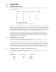
5.6 RNET COMPATIBILITY MODE
The DTX module can be programmed to mimic some of the behavior of the RNet 450 radio. In the RNet
compatibility mode, the CSN input is used as a channel selector line. A logic low selects channel 1 while a
logic high selects channel 2. The channel select lines, CS0, CS1, and CS2 have no effect. Also, the DCD
output is held in its true state during transmit. It would normally be false in transmit.
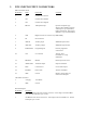
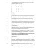
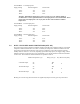
5.7 RECEIVER SELF-QUIETING SPUR (BIRDIE) FREQUENCIES (DTX-165)
Receiver self-quieting spurious signals (birdies) are internally generated signals that result from the
outputs and harmonics of the outputs of the various oscillators that form part of the DTX radio. These
usually sound like unmodulated carriers -- signals with "dead air." The DTX has two oscillators that tend
to cause birdies, the 14.4 MHz reference oscillator and the 12.288 MHz oscillator on the control/loader
board. Of these two, the 14.4 MHz is by far the most significant due to its proximity to the sensitive
receiver circuitry. Most of the spur frequencies in the following table have sensitivity degraded by 3 dB or
less. Frequencies where the sensitivity is degraded more than 4 dB below specification are in bold.
Frequencies that are integer multiples of the 14.4 MHz reference oscillator typically cause a reduction in
sensitivity of 10 dB or more and are in bold and in red. Note that a birdie is not the same thing as a
receiver spurious response. A spurious response is the receiver hearing a signal on a frequency other than
that to which it has been programmed.
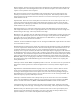
Self-Quieting Frequencies(MHz)
DTX-165