
User's Manual
5 OPERATION
5.1 CHANNEL SELECTION
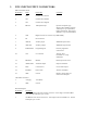
The DTX module supports eight channels. The desired channel is chosen via pins 1, 2, and 3 of the 15 pin
connector as shown:
Channel Pin 3 (CS2) Pin 2 (CS1) Pin 1(CS0)
1 0 0 0
2 0 0 1
3 0 1 0
4 0 1 1
5 1 0 0
6 1 0 1
7 1 1 0
8 1 1 1
0 = Logic low (0 to 0.3 VDC)
1 = Logic high (3.5 to 5.0 VDC or left unconnected)
A logic low is a voltage level below 1 volt while a logic high is a voltage level above 3.5 volts. These three
pins have an internal 10 k pull-up resistor to + 5 volts. Therefore, any pin left unconnected will assume a
logic high state. Do NOT apply voltages outside the range of 0 to +5 volts to these pins. Note: When the
Ritron programming cable is connected, these pins are not connected and thus, assume a logic high state.
Therefore, the radio will be on channel 8 when the Ritron programming cable is connected.
A change in the channel selection in receive will cause the receiver to operate on the new channel. In
transmit, however, the channel selection is only checked upon a push-to-talk activation. Changes in
channel during transmit will not change the transmit operating channel of the unit until the unit is cycled
from transmit to receive and back to transmit.
5.2 POWER SUPPLY VOLTAGE
The 2-pin Molex connector is the supply voltage input to the unit. One should be absolutely sure of the
proper voltage and current requirements before applying power.
The DTX-165, DTX-265, DTX-365, and DTX-465 units use 12.5 volt RF power modules. The supply
voltage can be at any voltage between 11 and 16 volts. Since the module is powered directly from this
voltage, the supply should be “clean” and, preferably, regulated. The output power will vary with supply
voltage. Switching power supplies can be used, but care must be taken that the output waveform is low
noise. Also, the module antenna should never be placed near an unshielded switching power supply.
5.3 CURRENT DRAIN VS SUPPLY VOLTAGE (DTX-165)
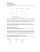
The current drain of the module is a function of the supply voltage and the RF output in transmit. Typical
current drain values are shown in the table below:
Receive Mode
Supply Voltage Internal Regulator Current Drain
11.0 V Yes 142 mA
12.5 V Yes 142 mA
16.0 V Yes 142 mA