
User's Manual

3 DTX INPUT/OUTPUT CONNECTORS
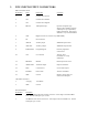
DB-15 Connector Pinout
Pin Number Name Description Comments
1 CS0 Channel Select low bit
2 CS1 Channel Select mid bit
3 CS2 Channel Select high bit
4 MIC IN Microphone Input Input for microphone type
signals to be transmitted. Signals
at this input are pre-emphasized,
limited, and filtered. This input is
disabled in very narrowband mode.
5 CSN High/Low Power or Channel 1/2 (in RNet Mode)
6 NC No Connection
7 AUX IN Auxiliary Input Wideband input for data.
8 AUX OUT Auxiliary Output Wideband output for data.
9 PGN IN/OUT Programming I/O External programmer
connects here.
10. CTS Clear to Send Asserted when
transmitter can accept
modulation.
11. RX MON Monitor Breaks squelch in receive.
12. AUDIO OUT Audio PA Output Output of audio PA.
13. DCD Carrier Detect Carrier detect output.
14. PTT/RTS Push to Talk Activates transmitter.
15. GND Ground Negative supply point and
reference for all inputs.
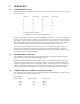
2-Pin Molex Connector
1 +Vsupply +10-16VDC
2 GND Ground
Pinout Description
Pin Number Description
1 CS0-Least significant bit of the channel select lines. Active high 5 volt TTL/CMOS
level. Internal 10 k pull-up to +5 volts.
2 CS1-Mid bit of the channel select lines. Active high 5 volt TTL/CMOS level. Internal
10 k pull-up to +5 volts.