RITRON, INC.
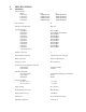
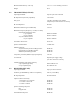
TABLE OF CONTENTS I DTX MODULES 1 INTRODUCTION 1.1 GENERAL 2 1.2 MODEL IDENTIFICATION 1.3 FCC REGULATIONS MODELS DTX-165 AND DTX-265 SPECIFICATIONS 2.1 GENERAL 2.2 TRANSMITTER 2.3 RECEIVER 3 DTX-165/265 INPUT/OUTPUT CONNECTOR 4 ACCESSORIES 5 OPERATION 5.1 CHANNEL SELECTION 6 5.2 POWER SUPPLY VOLTAGE 5.3 DUTY CYCLE/KEY-DOWN LIMITATIONS 5.4 OPERATING MODES 5.5 RNET COMPATIBILITY MODE PROGRAMMING 6.1 PC PROGRAMMING KIT 6.2 LOADING THE PROGRAMMING SOFTWARE 6.
10 ALIGNMENT 10.1 REQUIRED TEST EQUIPMENT 10.
1 INTRODUCTION 1.1 GENERAL The RITRON High Power DTX Plus modules are programmable 2-way radios, which operate either in the VHF or UHF professional FM communications bands as well as a number of other bands in the 220 MHz and 350 MHz region. Each of eight channels can be programmed to contain a unique set of operating frequencies. The High Power DTX Plus module is made up of two PC boards, an RF board and a control/loader board.
1.3 FCC REGULATIONS 1.3.1 LICENSING For those frequency bands governed by FCC rules, the FCC requires that the radio owner obtain a station license for his radio before using the equipment to transmit, but does not require an operating license or permit. The station licensee is responsible for proper operation and maintenance of his radio equipment, and for ensuring that transmitter power, frequency and deviation are within the limits specified by the station license.
Compliance with RF Exposure Standards: The DTX two-way radio is designed and tested to comply with a number of national and international standards and guidelines (listed below) regarding human exposure to radio frequency electromagnetic energy. This radio complies with the IEEE and ICNIRP exposure limits for general population/uncontrolled RF exposure environment at duty factors of up to 50% talk and 50% listen and is authorized by the FCC for occupational use.
• Use only a VHF quarterwave antenna or equivalent antenna or other antennas as specified in Table 1. Unauthorized antennas, modifications, or attachments could damage the radio and may violate FCC regulations. Approved Accessories • This radio has been tested and meets the FCC RF exposure guidelines when used with the Ritron accessories supplied or designated for this product. Use of other accessories may not ensure compliance with the FCC’s RF exposure guidelines, and may violate FCC regulations.
2 SPECIFICATIONS 2.
2.2 Maximum Dimensions (L x W x H) 6.6” x 5.0” x 2.4” including connectors Weight 35 oz. TRANSMITTER( DTX-165) Operating Bandwidth Up to the span of the sub-band RF Output Power (internally adjustable) 5 to 30 watts Duty Cycle 5 to 100 % depending upon ambient temperature(see chart elsewhere in manual) RF Load Impedance 50 ohms Modulation Distortion (per TIA/EIA 603) 5 % max.
FM Hum and Noise Very narrowband (5/6.25/7.5 kHz) operation Narrowband (12.5/15 kHz) operation Wideband (25/30 kHz) operation 40 dB min. 45 dB min. 50 dB min. Conducted Spurious -57 dBm max. Receive Attack Time (transmit to receive) 10 ms max. Carrier Detect Attack Time 5 ms max. Audio Distortion 5 % max.
3 DTX INPUT/OUTPUT CONNECTORS DB-15 Connector Pinout Pin Number Name Description 1 CS0 Channel Select low bit 2 CS1 Channel Select mid bit 3 CS2 Channel Select high bit 4 MIC IN Microphone Input 5 CSN High/Low Power or Channel 1/2 (in RNet Mode) 6 NC No Connection 7 AUX IN Auxiliary Input Wideband input for data. 8 AUX OUT Auxiliary Output Wideband output for data. 9 PGN IN/OUT Programming I/O External programmer connects here. 10.
3 CS2-Most significant bit of the channel select lines. Active high 5 volt TTL/CMOS level. Internal 10 k pull-up to +5 volts. Channel CS2 CS1 CS0 1 2 3 4 5 6 7 8 0 0 0 0 1 1 1 1 0 0 1 1 0 0 1 1 0 1 0 1 0 1 0 1 0 = Logic low 1 = Logic high Note: Due to the internal pull-up resistors, the unit defaults to channel 8 if the channel pins are left open (unconnected). Channel 8 would be the nominal channel when the Ritron programmer is connected. 4 MIC IN-Microphone input.
4 12 AUDIO OUT-This is the output of the audio power amplifier. This output can drive up to 100 milliwatts into an 8 ohm load. The output level can be controlled by programming. De-emphasis can be applied to this output, but not independently of the AUX OUT output. Note that this output level varies with the adjustment via the programmer of the AUX OUT level. Thus, the AUX OUT level should be set first before adjusting the AUDIO OUT level. 13 DCD-Carrier detect output.
5 OPERATION 5.1 CHANNEL SELECTION The DTX module supports eight channels. The desired channel is chosen via pins 1, 2, and 3 of the 15 pin connector as shown: Channel Pin 3 (CS2) Pin 2 (CS1) Pin 1(CS0) 1 2 3 4 5 6 7 8 0 0 0 0 1 1 1 1 0 0 1 1 0 0 1 1 0 1 0 1 0 1 0 1 0 = Logic low (0 to 0.3 VDC) 1 = Logic high (3.5 to 5.0 VDC or left unconnected) A logic low is a voltage level below 1 volt while a logic high is a voltage level above 3.5 volts.
Transmit Mode – 5 watt output power Supply Voltage Internal Regulator 11.0 V 12.5 V 16.0 V Yes Yes Yes Current Drain 2.2 A 2.3 A 2.4 A Warning: Although the output power can be set as low as 5 watts, and the module is certified as low as 5 watt, operation below 5 watts output power is not recommended. At low power levels, the output power can vary by 50% or more with variations in ambient temperature. Transmit Mode – 15 watt output power Supply Voltage Internal Regulator 11.0 V 12.5 V 16.
5.5 OPERATING MODES 5.5.1 RECEIVE Carrier Detect and Squelch Operation The DTX is a transceiver; i.e. it can receive and transmit, although not at the same time. A carrier detect system exists within the unit to detect the presence of a carrier which controls the logic state of the DCD (data carrier detect) output. The RF levels at which this output changes state are programmable.
Specialized Modem Operation Modems designed to achieve the highest data rates possible in a radio channel may require a direct DC connection to the modulation path and the removal of the limiter-filter. In order to receive FCC Certification, the DTX module must either be tested and approved with a specific modem connected to the transmitter, or a modulation limiter and limiter-filter must always be present in the transmit modulator audio path with the modulation inputs AC coupled.
6 PROGRAMMING To program DTX Module, the RITRON PC Programming Kit, DTXP2-PCPK-1, must be used. 6.1 PC PROGRAMMING KIT The user should install the programming software on the host computer. The RITRON adapter cables connect the radio to a computer’s serial communications port. Once the cables are hooked up, the user runs the programmer software. This program transfers data between radio and computer memory. 6.1.
6.5 PROGRAMMER MENUS The DTX Programmer has five menus or pages, selectable via tabs at the top of each page, which are always visible. These pages are: 1. Frequency-Used to program the channel frequencies of the radio. 2. Settings-Used to set programmable features/functions of the radio. 3. Alignment-Used to align and set the internal digital potentiometers in the radio. Information on the use of this page is found in the Maintenance section of the manual. 4.
RX De-emphasis- Allows for the signal path from the discriminator to the AUX OUT and Audio Out to be either de-emphasized or flat. Most applications where the AUX OUT output is used work best with a flat response. Factory default is for flat response. Busy Channel Lockout- Prevents the transmitter from activating when the carrier detect output is true. Used to prevent interference on a channel where activity already exists.
PTT/RTS Input Logic Level- Sets the polarity of the PTT/RTS input. Normally set for active low i.e. transmitter is activated when this input is at the logic low state. Due to the internal pull-up resistor, setting this to active high will cause activation of the transmitter when the PTT/RTS input is left unconnected. The factory default is active low. Green LED- Sets the operation of the green LED on the front of the radio. The choices are: a. Off-The green LED is never on. b.
achieve equal balance and deviation may differ. One can actually modify the calculated deviation and balance values per channel by entering values in the boxes, but this requires the services of a very qualified technician and the proper test equipment. The radio has been properly aligned at the factory and should not need to be adjusted. Details on how to perform these adjustments are found in the Alignment section.
II MAINTENANCE 10 IMPORTANT MAINTENANCE INFORMATION Surface Mount Repair: RITRON surface mount products require special equipment and servicing techniques. Improper servicing techniques can cause permanent damage to the printed circuit board and/or components, which is not covered by RITRON’s warranty. If you are not completely familiar with surface mount component repair techniques, RITRON recommends that you defer maintenance to qualified service personnel.
2) Board Separation Remove the two screws that secure the control/loader board to the rear bracket. The rear bracket stays connected to the RF board. Remove the two screws that secure the RF board to the front bracket. The front bracket stays connected to the control/loader board. These four screws are removed with a TORX T-9 driver. The two boards are held together by their interconnecting header/socket. Gently pry the two boards apart at the header/socket.
8 THEORY OF OPERATION 8.2 DTX-165 RF BOARD 8.2.1 RECEIVER RF amplifier and Bandpass Filters The incoming RF signal from the antenna connector passes backwards through the transmitter harmonic filter and to a diode switch. The diode switch, CR101, CR103, and CR201 route the RF signal to a lumped-element bandpass filter and then an amplifier Q101. The amplifier is followed by another lumpedelement filter.
8.2.2 Transmitter PA Driver Stages The output of the VCO buffer drives Q203 to provide a drive level to the RF PA device of about +17 dBm. The supply voltage to this stage is switched on in transmit by Q201 and Q202. PA Module, Lowpass Filter, and T/R Switch When driven by +17 dBm, the PA module, U201, is capable of producing full rated power at the antenna connector. Pin 2 of the module is used for power control.
8.3 CONTROL/LOADER BOARD The control/loader board is responsible for controlling the operation of the RF board and for processing the audio input and output signals to and from the RF board and to and from the outside. Audio Chain The audio processing, both transmit and receive, is handled by the audio Codec IC, U302 and the DSP microcontroller U301. These devices handle pre-emphasis, modulation limiting, and lowpass filtering on transmit as well as de-emphasis and filtering on receive.
10 ALIGNMENT Warning: Alignment must only be performed by qualified and trained service personnel. The DTX module is aligned at the factory before shipment and should need no further adjustment. It is possible that the gain settings for the audio input and output signal paths may need optimized. The frequency trim, deviation, and balance should not need adjustment. The procedure for performing all of the alignment steps is detailed below.
A channel with a receive frequency programmed into it should be selected. The correct local oscillator will be displayed on the programmer channel box. The frequency on the counter should be observed and the RX Frequency Trim value adjusted for least error. Because of the very low local oscillator level at the antenna terminals, the frequency counter may not be able to read the frequency.
10.2.7 TX FREQUENCY TRIM This setting is used to trim the transmitter to frequency. This value should not normally need adjustment. However, as the unit ages and/or if the transmitter power or the Aux In gain is changed significantly, slight corrections may be prudent. Note: Any adjustments must be made at a unit temperature of 25 +/- 2 C (77 +/- 1.8 F).