
User's Manual
2 CS1-Mid bit of the channel select lines. Active high 5 volt TTL/CMOS level.
Internal 10 k pull-up to +5 volts.
3 CS2-Most significant bit of the channel select lines. Active high 5 volt
TTL/CMOS level. Internal 10 k pull-up to +5 volts.
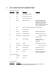
Channel CS2 CS1 CS0
1 0 0 0
2 0 0 1
3 0 1 0
4 0 1 1
5 1 0 0
6 1 0 1
7 1 1 0
8 1 1 1
0 = Logic low
1 = Logic high
Note: Due to the internal pull-up resistors, the unit defaults to channel 8 if the
channel pins are left open (unconnected). Channel 8 would be the nominal
channel when the Ritron programmer is connected.
4 MIC IN-Microphone input. This input accepts microphone-type input signals for
transmit. This input is a higher gain version of the AUX IN input. This input is not
available in very narrow channel mode.
5 CSN-Depending upon how it is programmed, this input selects between channels
1 and 2 or between high and low RF output power. This input is TTL/CMOS level
type input with a logic low required for channel 1/low power and a logic high
required for channel 2/high power. Internal 10 k pull-up to +5 volts.
6 NO CONNECTION.
7 AUX IN-This is the main audio input for modulation. The gain through this input
to the modulator is programmable, as is the use of pre-emphasis, but not
independently of the MIC IN. This signal passes through the clipper and clipper
filter.
8 AUX OUT-This is the broadband output of the receiver. The gain from the
receiver to the output is programmable, as is the use of de-emphasis. The
choice of AC or DC coupling from the RF board discriminator is also
programmable. The coupling at the output of this pin is AC coupled, however. It
can be converted to DC coupling with internal hardware modifications. Note:
The output impedance is approximately 600 ohms. Therefore, it is not
recommended that this output drive loads with less than 1000 ohms unless
the resultant voltage drop is accounted for.
9 PGN IN/OUT-Connect via RITRON DTXP-PCPK PC Programming Kit to
computer for programming the unit.
10 CTS-Clear-To-Send output from the unit which indicates that the unit is
transmitting a carrier at the correct frequency and power level and is ready to
accept an input signal to be transmitted. This output would normally become
asserted in response to a PTT RTS (see pin 14 description below) activation.
The polarity of this output can be programmed. The output is active low 5 volt
logic with an internal 10 k ohm pull-up to 5 volts. It can source up to 10 mA when
low.