RITRON, INC.
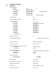
TABLE OF CONTENTS I DTX MODULES 1 INTRODUCTION 1.1 GENERAL 2 1.2 MODEL IDENTIFICATION 1.3 FCC REGULATIONS MODELS DTX-165 AND DTX-265 SPECIFICATIONS 2.1 GENERAL 2.2 TRANSMITTER 2.3 RECEIVER 3 DTX-165/265 INPUT/OUTPUT CONNECTOR 4 ACCESSORIES 5 OPERATION 5.1 CHANNEL SELECTION 6 5.2 POWER SUPPLY VOLTAGE 5.3 DUTY CYCLE/KEY-DOWN LIMITATIONS 5.4 OPERATING MODES 5.5 RNET COMPATIBILITY MODE PROGRAMMING 6.1 PC PROGRAMMING KIT 6.2 LOADING THE PROGRAMMING SOFTWARE 6.
9 HARDWARE OPTIONS 10 ALIGNMENT 10.1 REQUIRED TEST EQUIPMENT 10.
1 INTRODUCTION 1.1 GENERAL The RITRON High Power DTX Plus modules are programmable 2-way radios, which operate either in the VHF or UHF professional FM communications bands as well as a number of other bands in the 220 MHz and 350 MHz region. Each of eight channels can be programmed to contain a unique set of operating frequencies. The High Power DTX Plus module is made up of two PC boards, an RF board and a control/loader board.
Example: A DTX-265-OBN30I would be a VHF module for operation between 216 and 222 MHz with a BNC RF connector, narrow (12.5 kHz channel bandwidth) IF bandwidth, 30 watts maximum output power, and an internal regulator to allow operation from 10 to 15 volts. The part number system for a stand-alone RF board/Heat Sink assembly is the same as that for a module except that “F” designator (regulator option) does not exist and a “D” is appended at the end. 1.3 FCC REGULATIONS 1.3.
Federal Communications Commission Regulations: The FCC rules require manufacturers to comply with the FCC RF energy exposure limits for mobile 2-way radios before they can be marketed in the U.S. When 2-way radios are used as a consequence of employment, the FCC requires users to be fully aware of and able to control their exposure to meet occupational requirements. Exposure awareness can be facilitated by the use of a label directing users to specific user awareness information.
Table 1. Rated Power and Recommended Lateral Distance for quarter-wave ground plane antenna: Rated Power of DTX 2-way Radio Recommended Minimum Lateral Distance from Transmitting Antenna 5 watts or less: 30 to 5 Watts: 19.2 inches (48.7 cm) 35.3 inches (89.6 cm) Antennas • Install antennas taking into account the recommended minimum lateral distances in Table 1. These antenna installation guidelines are limited to antennas with appropriate ground planes.
2 SPECIFICATIONS 2.
2.2 Maximum Dimensions (L x W x H) 6.6” x 5.0” x 2.4” including connectors Weight 35 oz. TRANSMITTER( DTX-165) Operating Bandwidth RF Output Power Up to the span of the sub-band (internally adjustable) Duty Cycle 5 to 100 % depending upon ambient temperature(see chart elsewhere in manual) RF Load Impedance 50 ohms Modulation Distortion (per TIA/EIA 603) 5 % max.
Intermodulation Rejection 68 dB min. FM Hum and Noise Very narrowband (5/6.25/7.5 kHz) operation Narrowband (12.5/15 kHz) operation Wideband (25/30 kHz) operation 40 dB min. 45 dB min. 50 dB min. Conducted Spurious -57 dBm max. Receive Attack Time (transmit to receive) Carrier Detect Attack Time 10 ms max. 5 ms max. Audio Distortion 5 % max.
3 DTX INPUT/OUTPUT CONNECTORS DB-15 Connector Pinout Pin Number Name Description 1 CS0 Channel Select low bit 2 CS1 Channel Select mid bit 3 CS2 Channel Select high bit 4 MIC IN Microphone Input 5 CSN High/Low Power or Channel 1/2 (in RNet Mode) 6 NC No Connection 7 AUX IN Auxiliary Input Wideband input for data. 8 AUX OUT Auxiliary Output Wideband output for data. 9 PGN IN/OUT Programming I/O External programmer connects here. 10.
2 CS1-Mid bit of the channel select lines. Active high 5 volt TTL/CMOS level. Internal 10 k pull-up to +5 volts. 3 CS2-Most significant bit of the channel select lines. Active high 5 volt TTL/CMOS level. Internal 10 k pull-up to +5 volts. Channel 1 2 3 4 5 6 7 8 0 0 0 0 1 1 1 1 CS2 CS1 0 0 1 1 0 0 1 1 0 1 0 1 0 1 0 1 CS0 0 = Logic low 1 = Logic high Note: Due to the internal pull-up resistors, the unit defaults to channel 8 if the channel pins are left open (unconnected).
4 11 RX MON-This input breaks the squelch (unmutes) on the receiver i.e. allows for monitoring the channel even when a signal not strong enough to break squelch is present. Input levels are TTL/CMOS; polarity may be programmed. Internal 10 k pull-up to +5 volts. 12 AUDIO OUT-This is the output of the audio power amplifier. This output can drive up to 100 milliwatts into an 8 ohm load. The output level can be controlled by programming.
5 OPERATION 5.1 CHANNEL SELECTION The DTX module supports eight channels. The desired channel is chosen via pins 1, 2, and 3 of the 15 pin connector as shown: Channel 1 2 3 4 5 6 7 8 Pin 3 (CS2) 0 0 0 0 1 1 1 1 Pin 2 (CS1) 0 0 1 1 0 0 1 1 Pin 1(CS0) 0 1 0 1 0 1 0 1 0 = Logic low (0 to 0.3 VDC) 1 = Logic high (3.5 to 5.0 VDC or left unconnected) A logic low is a voltage level below 1 volt while a logic high is a voltage level above 3.5 volts.
Transmit Mode – 5 watt output power Supply Voltage Internal Regulator 11.0 V 12.5 V 16.0 V Yes Yes Yes Current Drain 2.2 A 2.3 A 2.4 A Warning: Although the output power can be set as low as 5 watts, and the module is certified as low as 5 watt, operation below 5 watts output power is not recommended. At low power levels, the output power can vary by 50% or more with variations in ambient temperature. Transmit Mode – 15 watt output power Supply Voltage Internal Regulator 11.0 V 12.5 V 16.
5.5 OPERATING MODES 5.5.1 RECEIVE Carrier Detect and Squelch Operation The DTX is a transceiver; i.e. it can receive and transmit, although not at the same time. A carrier detect system exists within the unit to detect the presence of a carrier which controls the logic state of the DCD (data carrier detect) output. The RF levels at which this output changes state are programmable.
Specialized Modem Operation Modems designed to achieve the highest data rates possible in a radio channel may require a direct DC connection to the modulation path and the removal of the limiter-filter. In order to receive FCC Certification, the DTX module must either be tested and approved with a specific modem connected to the transmitter, or a modulation limiter and limiter-filter must always be present in the transmit modulator audio path with the modulation inputs AC coupled.
6 PROGRAMMING To program DTX Module, the RITRON PC Programming Kit, DTXPNX-PCPK-1, must be used. 6.1 PC PROGRAMMING KIT The user should install the programming software on the host computer. The RITRON adapter cables connect the radio to a computer’s serial communications port. Once the cables are hooked up, the user runs the programmer software. This program transfers data between radio and computer memory. 6.1.
6.5 PROGRAMMER MENUS The DTX Programmer has five menus or pages, selectable via tabs at the top of each page, which are always visible. These pages are: 1. Frequency-Used to program the channel frequencies of the radio. 2. Settings-Used to set programmable features/functions of the radio. 3. Alignment-Used to align and set the internal digital potentiometers in the radio. Information on the use of this page is found in the Maintenance section of the manual. 4.
Audio Input- Allows a choice between the two audio inputs for transmit, the Aux In input and the Microphone input. As a rule, the microphone input has higher gain, but conversely, cannot accept as high an input level. If the Microphone input is selected, the Microphone Gain box to its right will allow a choice of two gain settings; there is no microphone gain setting available on the alignment page. Note that even if signals are applied to both inputs, only the one selected will be transmitted.
CSN Input- Controls the function of the CSN pin. This pin can be used to select one of two transmitter power levels in the High/Low Power position or can be used to select one of two channels in the RNET Channel 1/2 mode. See Section 5.6, RNET COMPATIBILITY MODE for details on this selection. CTS Output Logic Level- Sets the polarity of the CTS (Clear-To-Send) output. Setting for active high caused the true logic state to be high. Active high is the normal setting. The factory default is active high.
Carrier Detect On and Carrier Detect Off- Sets the carrier detect on and off values in dBm. For proper operation, always set the carrier detect on value to a higher level than the carrier detect off value. Typical values might be -100 dBm for carrier detect on and -114 dBm for carrier detect off. The difference between the two values represents the squelch hysteresis and is used to prevent squelch chatter when the receive signal is near the squelch setting values.
6.5.6 SAVING A CONFIGURATION Upon exiting the programmer via the exit button, the user will be presented with a box which allows the saving of the current configuration. This is useful if a number of other radios are to be programmed with the same frequencies and settings. If one does not wish to save the current configuration, the cancel icon should be selected. Also, if changes to the radio have been made via the programmer and the radio has not been updated, the user will be prompted to update the radio.
II MAINTENANCE 7 IMPORTANT MAINTENANCE INFORMATION Surface Mount Repair: RITRON surface mount products require special equipment and servicing techniques. Improper servicing techniques can cause permanent damage to the printed circuit board and/or components, which is not covered by RITRON’s warranty. If you are not completely familiar with surface mount component repair techniques, RITRON recommends that you defer maintenance to qualified service personnel.
2) Board Separation Remove the two screws that secure the control/loader board to the rear bracket. The rear bracket stays connected to the RF board. Remove the two screws that secure the RF board to the front bracket. The front bracket stays connected to the control/loader board. These four screws are removed with a TORX T-9 driver. The two boards are held together by their interconnecting header/socket. Gently pry the two boards apart at the header/socket.
8 THEORY OF OPERATION 8.2 DTX-165 RF BOARD 8.2.1 RECEIVER RF amplifier and Bandpass Filters The incoming RF signal from the antenna connector passes backwards through the transmitter harmonic filter and to a diode switch. The diode switch, CR101, CR103, and CR201 route the RF signal to a lumped-element bandpass filter and then an amplifier Q101. The amplifier is followed by another lumped-element filter.
8.2.2 Transmitter PA Driver Stages The output of the VCO buffer drives Q203 to provide a drive level to the RF PA device of about +17 dBm. The supply voltage to this stage is switched on in transmit by Q201 and Q202. PA Module, Lowpass Filter, and T/R Switch When driven by +17 dBm, the PA module, U201, is capable of producing full rated power at the antenna connector. Pin 2 of the module is used for power control.
8.3 CONTROL/LOADER BOARD The control/loader board is responsible for controlling the operation of the RF board and for processing the audio input and output signals to and from the RF board and to and from the outside. Audio Chain The audio processing, both transmit and receive, is handled by the audio Codec IC, U101, PMR processor U302, and the microcontroller U301.
9.2 RF BOARD OPTIONS 9.2.1 DISCRIMINATOR POLARITY The polarity of the discriminator output at pin 14 of J102 is configured at the factory such that an increase in RF frequency causes an increase in DC voltage. This is considered “normal” mode. An inverted mode is available where an increase in frequency causes a decrease in voltage.
10.2.1 RX FREQUENCY TRIM The RX Frequency Trim trims the unit on frequency during receive. This setting, if incorrect, may degrade receive sensitivity, distortion, and possible recovered audio level, which in turn affects AUX OUT (RX) Gain and Audio PA Gain. The receive frequency trim is not affected by any other alignment step. To determine if the receiver is correctly trimmed to frequency, the 1st local oscillator frequency must be measured.
10.2.5 TX LOW POWER AND HIGH POWER The transmitter output power level can be programmed on a per channel basis via the alignment page of the programmer. If RNet Compatibility has not been programmed on the settings page, both the low and high power levels can be set. If RNet Compatibility has been programmed, only high power can be set. The TX High Power and TX Low Power settings in the TX Power box act to select a common value for all channels.
On the channel drop-down menu, select lower band edge. Activate the PTT, and while observing the demodulated waveform on the oscilloscope, begin increasing the audio oscillator’s output level or the Aux In setting. The waveform should begin as a sinewave and at some point show clipping. The clipped portion may not necessarily be flat. The audio oscillator level should be set so that a substantial portion of the waveform is clipped, at least 50 %.