
User`s guide
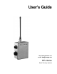

Installation/Operation DATAFLOW RTU
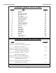
Installation/ Operation Table of Contents
SECTION TITLE PAGE NO.
1 Introduction A-1
2 Operation A-1
3 Microprocessor Updates A-1
4 Part Number Definition A-2
5 Accessories A-2
6 Specifications A-3
7 Control Board Schematic A-5
8 Control Board Layout A-6
9 RF Board Schematic A-9
10 RF Board Layout A-9
11 Interconnects A-9
12 Hardware Configuration A-11
13 Software Configuration A-12
14 Mounting Information A-12
15 Power A-14
16 Serial Link A-15
17 I/O Mapping A-15
18 Digital Inputs A-15
19 Digital Outputs A-16
20 Analog Inputs A-16
21 Analog Outputs A-17
22 Antennas A-19
23 Alignment A-19
24 Theory of Operation A-19
25 Voltage Charts A-21
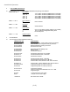
Installation/ Operation Table of Figures
TITLE PAGE NO.
Figure A1 - Control Board Schematic A-5
Figure A2 - Control Board Top Side Parts Placement
with Reference Designators A-6
Figure A3 - Circular Connector Pin Designations A-9
Figure A4 - Mounting Hole Pattern for Fastening
Directly to the DATAFLOW RTU Case A-12
Figure A5 - Mounting Hole Pattern for Use with
Optional Mounting Bracket A-13
Figure A6 - Battery Connection Wiring Diagram A-14
Figure A7 - Connecting a Current Loop Sensor to a
DATAFLOW RTU Analog Input A-17
Figure A8 - Connecting a Current Loop Indicator to a
DATAFLOW RTU Analog Output A-18
Software/ Programming (Part B) Table of Contents B - i
( A-v )