
User`s guide


DATAFLOW RTU
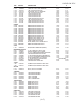
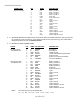
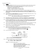
11.1.4 CONNECTIONS
CONNECTOR PIN NAME DESCRIPTION
Ext. Power/ Serial: 1 A Serial Pair A
J105 (X3.8 Y0.2) 2 B Serial Pair B
3 GND Loader Ground
4 LDR Loader Connected/ Program Enable
5 GND Power Ground
6 VI Power In to Controller and Radio
7 B+ From Internal Battery
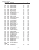
User Input/ Output: 1 R11 Relay 1 Contact 1
J101 (X1.8 Y0.3) 2 R21 Relay 2 Contact 1
3 R12 Relay 1 Contact 2
4 R22 Relay 2 Contact 2
5 PWR Power Out
6 GND Power Out Ground
7 S1 Input 1
8 GND Input 1 Ground
9 S2 Input 2
10 GND Input 2 Ground
11 S3 Input 3
12 GND Input 3 Ground
13 S4 Input 4
14 GND Input 4 Ground
15 S5 Input 5/ Output 1
16 GND Input 5/ Output 1 Ground
17 S6 Input 6/ Output 2
18 GND Input 6/ Output 2 Ground
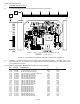
12. HARDWARE CONFIGURATION
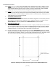
12.1 The DATAFLOW RTU has six hardware configurable jumpers. Jumper functions are described in the
following paragraphs 12.1.1 to 12.1.6. See Figure A2, page A-6, for location references.
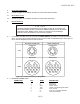
12.1.1 PJ101 (Y 2.8 - X 2.0): This jumper setting determines whether configurable I/O 1 is an input or an analog
output. The jumper across pins 1 and 2 configures the pin to be an input. The jumper across pins 2 and 3
configures the pin to be an output, the default setting.
12.1.2 PJ102 (Y 2.8 - X 1.8): This jumper setting determines if configurable I/O 2 is an input or an analog
output. The jumper across pins 1 and 2 configures the pin to be an input. The jumper across pins 2 and 3
configures the pin to be an output, the default setting.
12.1.3 PJ103 (Y 2.8 - X 1.6): This jumper setting determines how the configurable analog outputs 1 and 2 are
powered. The jumper setting is valid only if PJ101 or PJ102 is set for output. The jumper across pins 2
and 3 configures the output to be powered by system power. The jumper across pins 1 and 2 configures
the output to be powered by regulated radio power, the default setting.
PJ104 (Y 2.9 - X 1.2): This jumper setting determines if configurable I/O 1 is set for voltage or current loop
analog output. This jumper setting is valid only if PJ101 is set for output. With one jumper across pins 1
and 2 and another jumper across pins 3 and 4, the output is configured for voltage, the default setting.
Only one jumper across pins 2 and 3 configures the output for current loop.
( A-11 )