Users Guide http://www.dasieee.com e-mail: das@omega.
OMEGAnet® On-Line Service http://www.omega.com Internet e-mail info@omega.com Servicing North America: USA: ISO 9001 Certified Canada: One Omega Drive, Box 4047 Stamford, CT 06907-0047 Tel: (203) 359-1660 FAX: (203) 359-7700 e-mail: info@omega.com 976 Bergar Laval (Quebec) H7L 5A1 Tel: (514) 856-6928 FAX: (514) 856-6886 e-mail: info@omega.
WARRANTY/DISCLAIMER OMEGA ENGINEERING, INC. warrants this unit to be free of defects in materials and workmanship for a period of 13 months from date of purchase. OMEGA Warranty adds an additional one (1) month grace period to the normal one (1) year product warranty to cover handling and shipping time. This ensures that OMEGAs customers receive maximum coverage on each product. If the unit malfunctions, it must be returned to the factory for evaluation.
Installation/Operation/Software/Programming Manual DATAFLOW RTU OWNER INFORMATION FCC REGULATIONS LICENSING The FCC requires you to obtain a station license for your DATAFLOW RTU system before using it, but does not require an operation license or permit. The station licensee is responsible for ensuring that the transmitter power, frequency and deviation are within the limits specified by the station license. The licensee is also responsible for the proper operation and maintenance of the radio equipment.
Installation/Operation/Software/Programming Manual DATAFLOW RTU CAUTIONS 1. ALL DIGITAL INPUTS, ANALOG INPUTS, ANALOG OUTPUTS, AND MEASUREMENTS OF THE DATAFLOW RTU ARE REFERENCED TO GROUND. DO NOT USE THE DATAFLOW RTU WITH EQUIPMENT THAT REQUIRES COMPLETE ISOLATION. 2. ALL DATAFLOW RTU DIGITAL OUTPUTS ARE ISOLATED LATCHING RELAYS. DO NOT EXCEED CONTACT RATINGS OF THESE RELAYS. 3. EXCITATION VOLTAGE AND LOAD DRIVE VARY FROM MANUFACTURER TO MANUFACTURER.
Installation/Operation DATAFLOW RTU Installation/ Operation Table of Contents SECTION 1 2 3 4 5 6 7 8 9 10 11 12 13 14 15 16 17 18 19 20 21 22 23 24 25 TITLE PAGE NO.
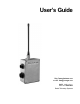
DATAFLOW RTU 1. INTRODUCTION 1.1 The DATAFLOW RTU from OMEGA is a complete wireless telemetry system designed to deliver industrial instrumentation signals from a source to other instruments via radio frequency communications. The DATAFLOW RTU allows you to access industrial measuring devices in remote locations without running wires, installing microwave links or leasing a telephone line. OMEGA DATAFLOW RTU and MODBUS radio communications equipment replaces these methods. 1.
Installation/Operation 4. 4.1 5. 5.1 PART NUMBER DEFINITION The following is a list of the part numbers available at the printing of this material. Band Option RTU-X X X - X / / / / 150- E 136-151 MHz. RF Board (OMEGA # DTX-150-E0DD) 150- 0 150-165 MHz. RF Board (OMEGA # DTX-150-00DD) 150- F 160-174 MHz. RF Board (OMEGA # DTX-150-F0DD) 450- 0 450-470 MHz. RF Board (OMEGA # DTX-450-00DD) 400- G 400-430 MHz.
DATAFLOW RTU 6 SPECIFICATIONS 6.1 SYSTEM SPECIFICATIONS FCC ID:......................................... Emission designator: RTU-150 - AIERIT04-150; RTU-450 - AIERIT04-450 10K8FID Digital Inputs:............................... LOW: HIGH: Maximum of 6 Programmable from 0 to 5 V Programmable from 0 to 5 V Digital Outputs:............................. UL/CSA rating: Two (2) isolated latching relays 2A 30VDC 0.5A 110VDC 0.5A 125VAC Analog Inputs: :.............................
Installation/Operation N O T E S ......................................................................................................................................................................... ................................................................................................................................................ .............................................................................................................................................. .....................
7. CONTROL BOARD SCHEMATIC 7.1 The following is the DATAFLOW RTU Control Board schematic.
Installation/ Operation 8. CONTROL BOARD LAYOUT 8.1 The following diagram shows the physical layout of the RTU control board X Y 1750090C 12/16/97 TOP SIDE PARTS PLACEMENT W/ REF. DES. 1750092G LAST ECN 2540 Figure A2 - Control Board top side parts placement with reference deisgnators. 8.2 EXAMPLE: The location of a particular component is given by the following notation - J101 PIN 1 (Y 0.3 - X 1.8). This means the pin 1 of connector J101 is located at a horizontal (X) coordinate of 1.
DATAFLOW RTU REF. DESCRIPTION Y 22uf 10V 6.0 X 3.2 CHIP TANTALUM CAP .33MF 35V "3.2X1.6" CHIP TANTALUM .1MF X7R 1206 50V CHIP CAP CAPACITOR .047F 5.5V TANTALUM .1MF X7R 1206 50V CHIP CAP .01MF X7R 0805 50V CHIP .01MF X7R 0805 50V CHIP .01MF X7R 0805 50V CHIP .01MF X7R 0805 50V CHIP .001MF X7R 0805 50V CHIP CAP .1MF X7R 1206 50V CHIP CAP .001MF X7R 0805 50V CHIP CAP .001MF X7R 0805 50V CHIP CAP .001MF X7R 0805 50V CHIP CAP 0.028 0.044 1.402 1.065 2.086 2.442 2.441 2.578 2.579 0.026 1.851 1.241 1.004 0.
Installation/ Operation REF. PART NO.
DATAFLOW RTU 9. RF BOARD SCHEMATIC 9.1 Contact Omega for more detailed information on the DTX RF board schematic. 10. RF BOARD LAYOUT 10.1 Contact Omega for more detailed information on the DTX RF board layout. 11. INTERCONNECTS C A U T I O N On DATAFLOW RTUs shipped before the 2nd quarter of 1998, do not exceed 6 volts referenced to GNDon RS-485 connections (the GREEN and BLUE wires of the External Power/Serial Cable: OMEGA Part No. 06001123).
Installation/Operation CONNECTOR PIN NAME DESCRIPTION User Input/ Output: 1 2 3 4 5 6 7 8 9 10 11 12 13 14 15 16 17 18 R11 R12 R21 R22 PWR GND S1 GND S2 GND S3 GND S4 GND S5 GND S6 GND Relay 1 Contact 1 Relay 1 Contact 2 Relay 2 Contact 1 Relay 2 Contact 2 Power Out Power Out Ground Input 1 Input 1 Ground Input 2 Input 2 Ground Input 3 Input 3 Ground Input 4 Input 4 Ground Input 5/ Output 1 Input 5/ Output 1 Ground Input 6/ Output 2 Input 6/ Output 2 Ground 11.1.
DATAFLOW RTU 11.1.4 CONNECTIONS CONNECTOR PIN NAME DESCRIPTION Ext. Power/ Serial: J105 (X3.8 Y0.2) 1 2 3 4 5 6 7 A B GND LDR GND VI B+ Serial Pair A Serial Pair B Loader Ground Loader Connected/ Program Enable Power Ground Power In to Controller and Radio From Internal Battery User Input/ Output: J101 (X1.8 Y0.
Installation/Operation 12.1.5 PJ105 (Y 2.7 - X 1.2): This jumper setting determines if configurable I/O 2 is set for voltage or current loop analog output. This jumper setting is valid only if PJ102 is set for output. With one jumper across pins 1 and 2 and another jumper across pins 3 and 4, the output is configured for voltage, the default setting. Only one jumper across pins 2 and 3 configures the output for current loop. 12.1.6 PJ106 (Y 0.2 - X 2.
DATAFLOW RTU 14.1.2 Optional mounting bracket OMEGA part number RTU-25104600 is available for DATAFLOW RTU. To install this bracket to the case, remove and save the four thread-forming screws described in paragraph 14.1 to attach the mounting bracket to the case. Be sure the narrow portion of the keyhole is positioned towards the top (UHF antenna connector) of the DATAFLOW RTU. Use the recommended hole pattern for the optional mounting bracket shown in Figure A5. .201 DIA. MIN.
Installation/Operation 15. POWER 15.1 The DATAFLOW RTU small enclosure (S) may be purchased with the delete internal power (D) option. The RTU power source is a user-provided external power supply meeting the following criteria: · Between 10 VDC and 16 VDC with 12 VDC nominal; · Has less than 1 V peak-to-peak of ripple; · Provides 1.5 A with the transmitter in low power setting; · Provides 2.5 A with the transmitter in high power setting. 15.1.
DATAFLOW RTU 15.5.3 The following calculations apply to RTU-BATNICD, using a 14V source. R1 = (14 - 0.4 - 12) / .05 = 32 W PR1 = (14 - 0.4 - 8)2 / R1 = 0.98 W 15.5.4 For RTU-BATHOLD, use a rechargeable battery type. Confirm the manufacturers specification for full charge voltage, empty voltage, and trickle charge current. 16. SERIAL LINK 16.1 J105 pins 1 and 2 comprises the pair of differential lines used for the RS-485 link.
Installation/Operation 19. DIGITAL OUTPUTS 19.1 The two digital outputs are defined to be pins 1-3 and 2-4. These outputs are two dry-contact closurelatching relays. They are controlled by the DATAFLOW RTU software, and are either OPEN or CLOSED. The following table defines the characteristics of the relay. The UL/ CSA power rating is the safe operating region. Operation outside of this region can damage the device. PARAMETER MINIMUM OPEN 1 MΩ CLOSED UL/ CSA POWER RATING MAXIMUM 1Ω 2A 30VDC .5A 110VDC .
DATAFLOW RTU USING DATAFLOW RTU AS THE EXCITATION VOLTAGE DATAFLOW RTU POWER OUT SENSOR ANALOG IN 250 Ω RESISTOR ANALOG IN GND USING AN EXTERNAL SOURCE AS THE EXCITATION VOLTAGE DATAFLOW RTU POWER OUT EXCITATION VOLTAGE V SENSOR ANALOG IN 250 Ω RESISTOR ANALOG IN GND Figure A7 - Connecting a Current loop sensor to a DATAFLOW RTU analog input. 20.2 All analog inputs are non-isolated. All analog measurements are referenced to GROUND. Take care when connecting the DATAFLOW RTU to external sensors.
Installation/Operation 21.1.2 If the output pin is to be a current sink, correctly set the hardware configuration. The pin is to be hardware configured as an output and as a current source. The following table defines the characteristics of the output pins set as a current sink. Attempting to drive a load less than the minimum will cause incorrect output and possibly can damage the device. See Figure A8, below, for an example of how to connect a current loop meter to the DATAFLOW RTU.
Software/Programming DATAFLOW RTU Software/ Programming Table of Contents SECTION 1 2 3 4 5 6 7 8 TITLE Introduction Operation Microprocessor Updates Programming Kit Programming Software MODBUS Memory Map Technical Notes Application Examples PAGE NO. B-1 B-1 B-1 B-1 B-3 B-11 B-13 B-15 Software/ Programming Table of Figures TITLE B1 B2 B3 B4 B5 B6 B7 B8 B9 B10 B11 B12 B13 PAGE NO.
DATAFLOW RTU 1. INTRODUCTION 1.1 The DATAFLOW RTU from OMEGA is a complete wireless telemetry system designed to deliver industrial instrumentation signals from a source to other instruments via radio frequency communications. The DATAFLOW RTU allows you to access industrial measuring devices in remote locations without running wires, installing microwave links or leasing a telephone line. OMEGA DATAFLOW RTU and MODBUS radio communications equipment replaces these methods. 1.
Software/Programming 4.2.1 The AC Power Supply, OMEGA part number RTU-PS, converts 110 Volts AC to a DC voltage for use by the DATAFLOW RTU. The power supply provides power to the RTU when RTU programming software is being used, and also provides power to the RTU, if it is to be connected to a MODBUS PC controller. CAUTION: Plug the power supply only into a 110 VAC outlet. AC Power Supply, OMEGA part number RTU-PS is intended only for indoor use at normal room temperatures.
DATAFLOW RTU 4.2.4 RTU Programming Software Disk, OMEGA part number RTU-PCPS-3.0, provided with the programming kit to facilitate configuration of a DATAFLOW RTU is version 3.0. To install it on the computer hard drive, insert the 3.5" diskette into the floppy drive, select that drive and type INSTALL.EXE. Follow the instructions on the computer monitor screen to load the software onto the hard drive.
Software/Programming 5.5 The , and function keys are used in several fields of the programming software to perform file functions. The READ DISK key transfers file data from the computer hard disk to the computer screen field values. The WRITE DISK key transfers file data from the computer-screen field values to the computer hard disk. The DIR key displays all files of the proper type that are on the computer hard disk.
DATAFLOW RTU >>> RTU PROGRAMMER VERSION 3.03 960724 HELP FILE <<< 1.0 RTU System Configuration Screen: The system configuration screen provides an area for the user to configure system parameters, send list, repeat list, and fail-safe states. It allows access to RTU configuration and disk files. It also provides access to the input/output configuration and the SCADA configuration. 1.1 System Parameters: The frequency must be the same for all RTUs in a system.
Software/Programming >>> RTU PROGRAMMER VERSION 3.03 HELP FILE <<<(continued) Enabling RF spy mode on one RTU allows that RTU to report all incoming RF messages over the serial link. These messages can be displayed using the RF Spy screen available from the Utilities menu. While the RF Spy feature is enabled, the unit will only operate in RF Spy mode and will not respond to the RF messages. 1.2 Send List: The send list indicates up to four other RTUs to which this RTU can send its status.
DATAFLOW RTU >>> RTU PROGRAMMER VERSION 3.03 HELP FILE <<<(continued) 1.5 Message Line The third line from the bottom of the RTU system configuration screen is the message line. This line displays important information about the status of uploads, downloads, disk reads, and disk writes. 1.6 Function Keys The last two lines of the RTU system configuration screen form the function key menu. To perform one of the listed tasks either press the related function key or click the command with your mouse.
Software/Programming >>> RTU PROGRAMMER VERSION 3.03 HELP FILE <<<(continued) If this input is selected as a Digital input, the value in this field will be a threshold. Any value above this threshold will be a 1 and any value below this threshold will be a zero. A message is created only when the input crosses from one side of the threshold to the other. If the input type is analog, the value in this field is a dead zone. The dead zone is minimum change necessary to initiate a message.
DATAFLOW RTU >>> RTU PROGRAMMER VERSION 3.03 HELP FILE <<<(continued) Input Tag Name Initiate Xmit Type Invert Threshold / Dead Zone Time Delay # 1 # 2 # 3 # 4 # 5 # 6 BATTERY YES D YES 50 % YES A NO 10 % NO D NO 50 % NO D NO 50 % NO D NO 50 % NO D NO 50 % NO A NO 1.00 V 5.00 S 0.25 S 0.25 S 0.25 S 0.25 S 0.25 S 0.
Software/Programming >>> RTU PROGRAMMER VERSION 3.03 HELP FILE <<<(continued) 3.1 EEPROM SCADA Points Four SCADA points can be stored in EEPROM. If power to the RTU is temporarily lost and then returns, the EEPROM points will not be lost. The repeater columns list, in order, the repeaters between this RTU and the End RTU. The To ID is the RTU or other MODBUS device which the SCADA program will request information from. If the To ID is an RTU, the To ID and End RTU will be identical.
DATAFLOW RTU 6. MODBUS MEMORY MAP 6.1 The DATAFLOW RTU supports three types of MODBUS messages; it will recognize: · · · READ OUTPUT REGISTER function code 03 PRESET SINGLE REGISTER function code 06 PRESET MULTIPLE REGISTER function code 10 (hexadecimal). All other messages will be ignored. 6.2 The DATAFLOW RTU operates in the MODBUS RTU mode with 8 data bits, 1 stop bit and no parity bit. 6.
Software/Programming 6.3.2 DECIMAL MODBUS MEMORY MAP AND TABLES 6.3.2.1 Decimal MODBUS memory map for stored data access: RTU ID 0 1 2 3 · · · 253 254 255 6.3.2.
DATAFLOW RTU 6.4 Load the FULL SCADA CONFIG, using RTU Programming Software. The configuration is stored in RTU RAM, which has a large capacitor to hold the information in memory for an extended period of time 3 months or longer. If the stored configuration is lost, reload it with the RTU Programming Software. 6.4.1 If the application requires a MODBUS controller to download the FULL SCADA CONFIG, consult OMEGA for the proper procedure.
Software/Programming 7.2 COPYING CONFIGURATION between DATAFLOW RTU Units: This note explains how to preserve programmed default settings. TO COPY CONFIGURATION FROM AN OLDER-FIRMWARE DATAFLOW RTU TO A NEWERFIRMWARE DATAFLOW RTU, while preserving the default settings of additional programmable features: 7.2.1 Connect older-firmware unit to the serial cable and power supply. 7.2.2 From the Programmer Main Screen, press 2 to select DATAFLOW RTU configuration. 7.2.3 Press F3 to Upload. 7.2.
DATAFLOW RTU EXAMPLE 1 8.2 EXAMPLE 1 is a pair of DATAFLOW RTUs having two digital channels and two analog channels in each direction; each RTU is configured for a maximum of five (5) message attempts. If an RTU detects loss of RF link, both relay outputs close, and both analog outputs are driven to full scale.
Software/Programming EXAMPLE 1 (continued) 8.2.3.3 The FAIL-SAFE STATE table controls RTU outputs when the RTU detects a loss of RF link. Because Example 1 has only one entry in the SEND LIST of each RTU, only FAILSAFE STATE A is used. If RTU ID 1 detects loss of RF link, RTU ID 1 outputs are controlled according to its FAIL-SAFE STATE A; if RTU ID 2 detects loss of RF link, RTU ID 2 outputs are controlled according to its FAIL-SAFE STATE A. 8.2.3.3.
DATAFLOW RTU EXAMPLE 2 8.3 EXAMPLE 2 configures three DATAFLOW RTUs with one connected to two others. RTU ID 1 has two digital inputs, two digital outputs and two analog outputs. RTU ID 2 and RTU ID 3 each have one digital input, one digital output and one analog input.
Software/Programming EXAMPLE 2 (continued) 8.3.4.2 The FAIL-SAFE STATE table controls the RTU outputs when the RTU detects a loss of RF link. Because Example 2 has two entries in the SEND LIST, both FAIL-SAFE states A & B are used. If RTU ID 1 detects a loss of RF link from RTU ID 2, outputs are controlled according to FAIL-SAFE STATE A. If RTU ID 1 detects a loss of RF link from RTU ID 3, outputs are controlled according to FAIL-SAFE STATE B. 8.3.4.
DATAFLOW RTU EXAMPLE 3 8.4 EXAMPLE 3 configures DATAFLOW RTU inputs to illustrate THRESHOLD, DEAD ZONE and TIME DELAY. The configuration includes Digital Input 1 having a 25% Threshold and Digital Input 2 having a 75% Threshold and a 5-second Time Delay; Analog Input 3 having a 10% Dead Zone and Analog Input 2 having a 20% Dead Zone. The configuration of Example 3 is similar to that of Example 1. 8.4.
Software/Programming EXAMPLE 4 8.5 EXAMPLE 4 configures two RTUs to illustrate XMIT CHECK-IN and RCV CHECK-IN intervals, and R (Revert) FAIL-SAFE STATE of the DATAFLOW RTU. RTU ID 1 sends one contact closure to RTU ID 2. All Digital Outputs are OPEN at power-on. · When RTU ID 1 detects a loss of RF link, both Digital Outputs close. When the RF link is re-established, Digital Output 1 opens and Digital Output 2 remains closed.
DATAFLOW RTU EXAMPLE 5 8.6 EXAMPLE 5 illustrates a DATAFLOW RTU system with one RTU configured as a repeater.
Software/Programming EXAMPLE 6 8.7 EXAMPLE 6 demonstrates the DATAFLOW RTU as a MODBUS device using direct data access. The configuration consists of a remote RTU with another RTU connected to a MODBUS controller, utilizing RTU Programming Software as the MODBUS controller. Each RTU has five digital inputs and one analog input. NOTE: In real applications the MODBUS controller is a PLC or a SCADA program operating with a MODBUS driver. 8.7.
DATAFLOW RTU EXAMPLE 6 (continued) 8.7.5 Execute the SYSTEM MONITOR - UTILITIES screen to view two ID fields: The top left field on the UTILITIES screen selects which RTU is active when polling inputs or setting outputs. This field is the only field used in Example 6 configuration. · · · · Set this ID to 1, then execute the SINGLE POLL command. The current input status of RTU ID 1 displays on the screen. Change the ID to 2, then execute the SINGLE POLL command.
Software/Programming EXAMPLE 7 8.8 EXAMPLE 7 demonstrates the DATAFLOW RTU as a MODBUS device using stored data access. The configuration consists of a remote RTU with another RTU connected to a MODBUS controller. Example 7 uses RTU Programming Software as the MODBUS controller. The remote RTU and the RTU connected to the MODBUS controller each have five digital inputs and one analog input. NOTE: In real applications the MODBUS controller is a PLC or a SCADA program operating with a MODBUS driver. 8.8.
DATAFLOW RTU EXAMPLE 8 8.9 EXAMPLE 8 illustrates the DATAFLOW RTU performing a MODBUS modem function. Configuration files EXP8ID1 and EXP8ID2 allow two MODBUS devices to communicate with each other by RF. This configuration can connect two PLCs (MODBUS protocol) to communicate with each other over RF, as long as one PLC is a master and the other is a slave with an ID of 3. No set-up or wiring diagram is provided with this example. 8.9.
Software/ Programming Figure B1 - EXAMPLE 1 RTU ID 1 Wiring Diagram RITRON, INC.
DATAFLOW RTU Figure B2 - EXAMPLE 1 RTU ID 2 Wiring Diagram ( B-27 ) RITRON, INC.
Software/ Programming Figure B3 - EXAMPLE 2 RTU ID 1 Wiring Diagram RITRON, INC.
DATAFLOW RTU Figure B4 - EXAMPLE 2 RTU ID 2 Wiring Diagram ( B-29 ) RITRON, INC.
Software/ Programming Figure B5 - EXAMPLE 2 RTU ID 3 Wiring Diagram RITRON, INC.
DATAFLOW RTU Figure B6 - EXAMPLE 4 RTU ID 1 Wiring Diagram ( B-31 ) RITRON, INC.
Software/ Programming Figure B7 - EXAMPLE 4 RTU ID 2 Wiring Diagram RITRON, INC.
DATAFLOW RTU Figure B8 - EXAMPLE 5 RTU ID 1 Wiring Diagram ( B-33 ) RITRON, INC.
Software/ Programming Figure B9 - EXAMPLE 5 RTU ID 2 Wiring Diagram RITRON, INC.
DATAFLOW RTU Figure B10 - EXAMPLE 5 RTU ID 3 Wiring Diagram ( B-35 ) RITRON, INC.
Software/ Programming Figure B11 - EXAMPLE 6 RTU ID 1 Wiring Diagram RITRON, INC.
DATAFLOW RTU Figure B12 - EXAMPLE 6 RTU ID 2 Wiring Diagram ( B-37 ) RITRON, INC.
Where Do I Find Everything I Need for Process Measurement and Control? OMEGA Of Course! TEMPERATURE Thermocouple, RTD & Thermistor Probes, Connectors, Panels & Assemblies Wire: Thermocouple, RTD & Thermistor Calibrators & Ice Point References Recorders, Controllers & Process Monitors Infrared Pyrometers PRESSURE, STRAIN AND FORCE Transducers & Strain Gauges Load Cells & Pressure Gauges Displacement Transducers Instrumentation & Accessories FLOW/LEVEL Rotameters, Gas Mass Flowmeters & Flow Computers Air Ve