
Installation manual


Rinnai Australia 31 Installation Manual
HEATER INSTALLATION
Step 10. COMMISSION THE APPLIANCE
240 VOLTS, RISK OF ELECTRICAL SHOCK!
When performing the commissioning, the appliance electrical power will need to be
connected. Exercise CAUTION as there is potential for electric shock from the
exposed wiring and circuitry. DO NOT leave the appliance unattended when power is
connected and the panels are removed.
Installation and commissioning must be carried out by an Authorised person.
Wiring inside this appliance may be at 240V potential.
DO NOT test for gas escapes with an open flame.
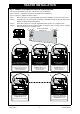
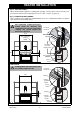
To check and set burner pressures:
1. Refer to the appliance data plate located inside the appliance on the front of the base panel for
correct gas pressure settings.
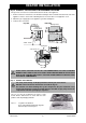
2. Using a suitable screw driver loosen the captive
Appliance Test Point Pressure screw (ATPP)
and fit the manometer, (an electronic manometer
is recommended). Refer images for ATPP
location.
3. Remove the dust cap from the regulator
adjusting screws.
4. High Pressure Setting:
Turn the appliance ‘ON’ and adjust to the highest
setting, see ‘How to Operate Your Heater’ section
page 11. Use a 10 mm spanner to turn nut ,
lock screw with appropriate screw driver to
prevent it turning. Turning nut clockwise
increases the outlet pressure whilst turning anti-
clock wise decreases the outlet pressure.
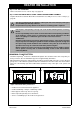
5. Low Pressure Setting:
Turn ‘OFF’ the power to the POV by separating
the connector of the two yellow wires that power
the POV. The POV will automatically default to
‘Low Pressure’ operation. Keep the high pressure
adjusting nut stationary using a 10 mm spanner.
Use an appropriate screwdriver for setting screw
. Turning clockwise increases the outlet
pressure whilst turning anticlockwise decreases
the outlet pressure.
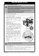
6. Replace the dust cap after pressure
adjustments.
7. Reconnect the POV Yellow wires power
connection.
To ensure the correct operation of the modulating valve (POV) it is necessary that the
dust Cap C is returned to its original location.
8. After re-checking the pressures, turn the appliance ‘OFF’, remove manometer and tighten the
test point sealing screw.
9. Turn the appliance ‘ON’ and ‘OFF’ a few times to confirm correct ignition and operation.
10. During the initial burn in period, some smoke and smell may be emitted. The appliance should be
run on the high position in a well ventilated room until these dissipate.
11. Check the flame pattern, see ‘Abnormal Flame Pattern’, section page 16 and page 33.
WARNING
D
C
A
B
A
B
C
A
B
GAS
OUTLET
GAS CONTROL AND IGNITION PACK ASSEMBLY
APPLIANCE OUTLET
TEST POINT PRESSURE
B
A
C
D
INLET
TEST POINT
CAP
HIGH PRESSURE
ADJUSTING NUT
LOW PRESSURE
ADJUSTING SCREW
WARNING