
Installation manual

Rinnai Australia 21 Installation Manual
HEATER LOCATION
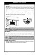
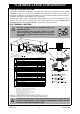
ELECTRICAL SUPPLY
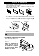
• This heater is supplied with a power cord (length 1500
mm) and three pin plug. The power cord passes
through the right hand side panel as shown. Rinnai
recommend the heater be plugged into a 240V, 10A
earthed power point. The power point must not be
above the heater.
A suitable means of electric isolation must be provided
which is adjacent to the appliance and accessible with
the appliance installed, in accordance with AS/NZS
5601.
• The appliance can be direct wired if the power supply is
to be concealed. An isolator switch MUST be used in
accordance with AS/NZS 5601 & AS3000.
Consult a qualified electrician if direct wiring is required as it must comply with
the requirements of AS/NZS 5601 & AS3000 and any other relevant local
regulations.
The electrical cord must not come into direct contact with the heated parts of the
appliance or flue system.
If the power cord is damaged and requires replacing, it must be replaced by a
licensed tradesperson. It must be a genuine replacement part available from
Rinnai.
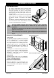
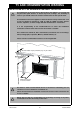
ENCLOSURE REQUIREMENTS
RDV3610ETR
The appliance must be positioned on a flat level
surface. As this appliance has a cool outer casing it
can be installed into a decorative fireplace
constructed from materials such as wood or plaster.
The only exception is the cladding above the
appliance which must be non-combustible and
extend at least 400 mm above the appliance in
accordance with the drawings on page 3, page 20
and page 32.
If the appliance is elevated from the ground, a base
must be constructed using suitable material with
supporting joists, capable of easily supporting a
minimum of 175kg. (Flue must be supported
independently of the appliance).
RDV3611ETR
Cladding material need not be non-combustible.
Ensure construction is in accordance with drawings
on page 3, page 20 and page 32.
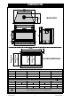
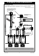
ENCLOSURE DIMENSIONS
Enclosure dimensions are shown below. The
enclosure dimensions specified are critical to the
successful installation of this appliance and must be
strictly adhered to.
Typical Frame Layout
Corner Installation Layout
IMPORTANT
1
1
0
0
~
1
1
2
5
6
0
0
m
i
n
850 min
1
2
9
5
m
m
915 mm
183
0 mm