
Installation guide

RDV3611 Installation Manual: 11156-A 01-12 | 17
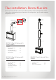
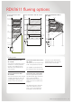
RDV3611 ueing options
Min. 0.9 m
3.0 m
Max. 5.4 m
Max. 1.8 m
4.2 m
1.8 m
No restrictor
Restrictor position # 2
Restrictor position # 3
Restrictor position # 4
Min. 0.9 m
4.2 m
Max. 5.4m
Max. 3.5 m
Restrictor position # 2
1.8 m
3.0 m
Restrictor position # 3
Restrictor position # 4
No restrictor
Min. 0.6 m
after bend
Min. 0.9 m
2.4 m
4.2 m
Max. 5.4 m
Min. 0.3 m
Max. 3.5 m
Max. 0.9 m
Max. Horizontal =(6.03-Vertical)/0.52
Max. Horizontal = Vertical/0.692
Max. 1.2 m
No restrictor
Restrictor position # 3
Restrictor position # 4
Vertical termination with
45 ° bends
Vertical termination with 90 ° bends Horizontal termination with a
90 ° bend
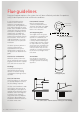
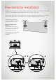
Flueing notes
Vertical termination with
45 ° bends
Vertical flue terminations with or
without 45 ° bends (maximum
of two). The shaded sections
determine the position of the
flue restrictor.
Vertical termination with
90 ° bends
Vertical terminations with two 90
° bends (maximum of two). The
shaded regions determine the
position of the flue restrictor.
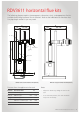
Horizontal termination with a
90 ° bend
Horizontal flue terminations with
a 90 ° bend (maximum of one).
The shaded sections determine
the position of the flue restrictor.
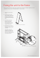
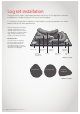
Horizontal runs of flue pipe
Must be supported to prevent
any downward sags. Horizontal
pipe sections should be
supported at least every 1.2 m.
Wall straps can be used for this
purpose.
The horizontal run of flue pipe
must have a 20 mm rise for
every 1 m of run towards the
termination. Never allow the
flue pipe to run downward. A
downward slope can trap heat
and become a fire hazard.