
Operating instructions


Table Of Contents
Rinnai New Zealand Ltd. RDV36 Heat Transfer Kit Installaon 11700-E 05-11
5
Installer informaon
General guidelines regarding installation
Before installation
• Check for damage—do not install any damaged items
• Check all components have been supplied, refer kit contents on following page
• Read these instructions to get an overview of the steps required before starting
6 m (cannot be cut)
6 m (cannot be cut)
3 m
3 m
All duct bends to be kept as smooth as possible
The heat transfer kit has been specically designed and tested as a 9 m kit. Ducting length can
be increased by joining two kits together, however, some heat loss may occur.
The rst 6 m duct length must be positioned between the Symmetry and the fan. It must not
be cut down. This is to ensure excessive heat does not run through the fan. Do not cut the 3 m
section of duct that connects the fan to the heat outlet—doing this may create excessive fan
noise.
Connection outlets for the heat ducting kits are on the right and left hand side of the replace.
Two heat ducting kits—one on each side can be attached to the Symmetry unit.
Any bends in the ducting should be as smooth as possible so as not to restrict air ow. The
insulated ducting has zero clearance to combustibles.
Ducting and bends should be supported as necessary—with wire from rafters etc. (W)
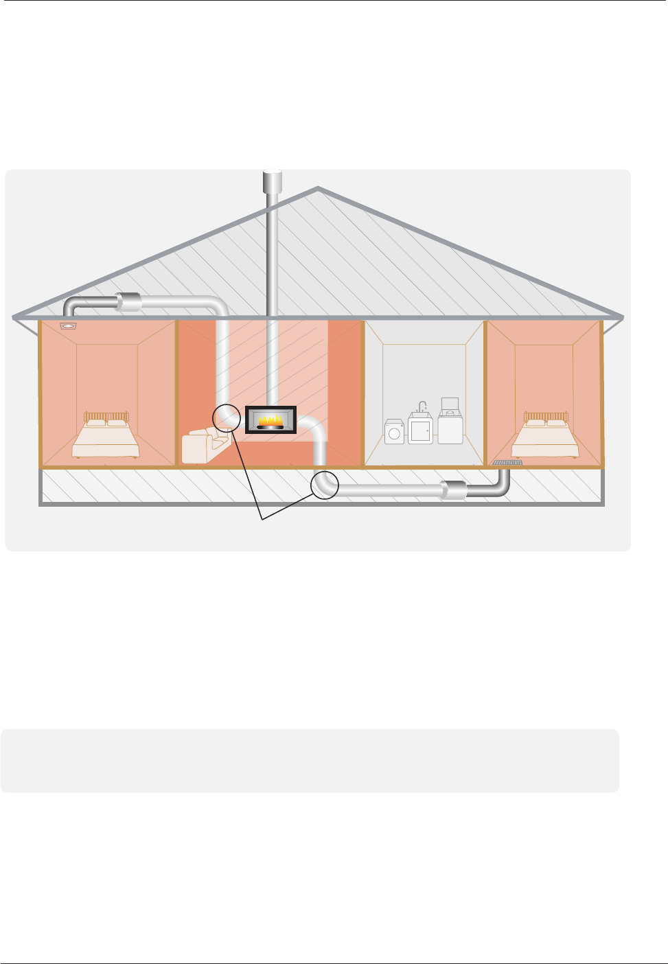
Example of two Symmetry heat transfer kits joined together
6 m (must not be cut down) + fan + 3 m + 6 m (can be cut down) + fan + 3 m = 18 m