
Installation manual


Rinnai New Zealand Limited RDV3610 Installation Manual: 11658-E
05-10
21
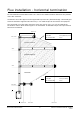
Flue installation - horizontal termination
For horizontal ue terminations with a 90 ° bend. The shaded sections determine the position
of the ue restrictor.
Horizontal runs of ue pipe must be supported to prevent any downward sags. Horizontal pipe
sections should be supported at least every 1.2 m. Wall straps can be used for this purpose.
The horizontal run of ue pipe must have a 20 mm rise for every 1 m of run towards the
termination. Never allow the ue pipe to run downward. A downward slope can trap heat and
become a re hazard.
Min. 0.6 m
2.4 m
4.2 m
Max. 5.4 m
Min. 0.3 m
Max. 3.5 m
Max. 0.9 m
Restrictor posion # 3
Max. Horizontal =(6.03-Vercal)/0.52
Max. Horizontal = Vercal/0.692
Max. 1.2 m
Restrictor posion # 4
No restrictor
Example
Vercal ue: 5.0 m (6.03-5.0) ÷ 0.52
Max. horizontal ue: 2.0 m
Example
Vercal ue: 2.0 m (2 ÷ 0.692)
Max. horizontal ue: 2.9 m