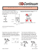
How to use your New Continuous Flow Commercial Water Heater Model 2424WC (outdoor unit) WARNING: If the information in these instructions is not followed exactly, a fire or explosion may result causing property damage, personal injury or death. -Do not store or use gasoline or other flammable vapors and liquids in the vicinity of this or any other appliance. -WHAT TO DO IF YOU SMELL GAS * Do not try to light any appliance.
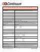
S P E C I F I C A T I O N S Type of appliance Temperature controlled continuous flow gas hot water system Operation With or without remote controls Exhaust system Direct Vent - Forced combustion Rinnai model number REU-2424WC-US Maximum/Minimum gas rate (Input BTU's) 180,000 BTU's - 19,000 BTU's Hot water capacity (50°F rise) 0.6 to 6.
S P E C I F I C A T I O N S Appliance - AC 120 Volts - 60Hz. Remote control DC 12 Volts (Digital) Flame failure - Flame rod Boiling protection - 203°F Remaining flame (OHS) 194°F bi-metal switch Safety devices Thermal fuse 279°F Automatic frost protection - Bi metal sensor & anti-frost heaters Combustion fan rpm check - Integrated circuit Over current - Glass fuse (3 amp) If remote fails or becomes disconnected unit defaults to 100°F with water flowing, this is an anti-scald feature.
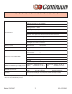
W A R R A N T Y Rinnai warrants the continuous Commercial Water Heater Model 2424WC, including any parts and components thereof, to be free from any defects in materials and workmanship for the period specified below, subject to the terms specified in this warranty. This warranty gives you specific legal rights and you may also have other rights which vary from state to state.
C O N T E N T S Specifications .............................................................. 2,3 Warranty ........................................................................ 4 Owner's Installation Information ................................... 6 Features of your new Continuum ................................ 7 Safety Issues .............................................................. 8,9 Basic Operation ........................................................... 10 About Hot Water .........
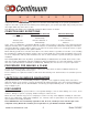
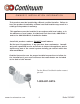
O W N E R ’ S I N S TA L L AT I O N I N F O R M AT I O N This product must be installed by a Rinnai certified installer. Failure to have the product installed by a Rinnai certified installer may result in a voiding of the product’s warranty. This appliance must be installed in accordance with local codes, or in the absence of local codes, the National Fuel Gas Code, ANSI Z223.1 and/or the CAN/CGA-B149, Installation Codes. Install this product outdoors, DO NOT install indoors.
F E AT U R E S O F Y O U R N E W C O N T I N U U M ) ) ) ) ) ) ) ) ) ) The Continuum 2424WC is one of the most advanced water heaters available. It supplies hot water continuously at the temperature preset in the unit or at the temperature set on the optional remote control. The remote control is recommended for optimum performance. The Continuum 2424WC never runs out of hot water. While electricity, water and gas supplies are connected, hot water is available whenever the hot tap is open.
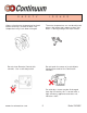
S A F E T Y I Always check water temperature by hand before entering a shower or bath. The temperature may have been changed. S S U E S The water temperature can not be adjusted when a hot water tap is open or when hot water is flowing through the water heater. Do not clean Remote Control with solvents. Use a soft damp cloth. Do not touch the cover or insert objects into the flue outlet of the Continuum 2424WC.
S A F E T Y I If the external Continuum 2424WC is disconnected from the power supply and freezing conditions are expected, turn off water and gas, and drain all water from the appliance. S S U E S Keep flammable materials, trees, shrubs etc. away from the Continuum 2424WC. Water Off Gas Off DRAIN Drain Water FILTER Do not spray water directly into the flue terminal. WATER GAS If power and the automatic frost protection are connected, freezing will be prevented in conditions as cold as -30°F.
B 1 A S I C O P E R A T I O N 2 Adjusting Temperature The setpoint temperature of the Continuum 2424WC can only be adjusted by the user using the Remote Control. To adjust the setpoint temperature of the Continuum 2424WC, all hot water taps must be closed, and all circulating pumps turned off. TEMPERATURE CANNOT BE ADJUSTED WHEN ANY HOT WATER TAP IS OPEN, OR WATER IS FLOWING THROUGH THE WATER HEATER.
A B O U T H O T W A T E R Hot Water Is Dangerous, especially for the young and the elderly or the infirm. The Continuum 2424WC allows you to precisely control the temperature of your hot water, ensuring safe hot water temperatures. Water Temperatures over 125°F can cause severe burns instantly or death from scalds.
R E M O T E C O N T R O L O P E R AT I O N Digital Monitor In Use Indicator Indicates the selected water temperature. Error messages flash in the event of a failure. Indicates that a hot water tap is open. (The setpoint temperature cannot be adjusted when indicator is illuminated.) Maintenance Button Maintenance °F M Set Temperature In Use C Main Controller MCC - 45 - 3US Pressing repeatedly shows sequence of error codes water heater has experienced.
E R R O R M E S S A G E S The Continuum 2424WC has the ability to check its own operation continuously. If a fault occurs, an Error Message will flash on the Digital Monitor of the Remote Controls. This assists with diagnosing the fault, and may enable you to overcome a problem without a service call. Please quote the code displayed when inquiring about service. NOTE: Failure to remedy faults may result in severe burns, scalds, and/or death.
M A I N T E N A N C E & S E R V I C E I N F O R M AT I O N Warning: Always turn off the electrical power supply, the manual gas valve and the manual water control valve whenever servicing the unit. The Continuum 2424WC should be checked by a Rinnai Certified Technician once a year. A Rinnai Certified Technician should perform any repairs that may be necessary.
M A I N T E N A N C E & S E R V I C E I N F O R M AT I O N MAINTENANCE SUGGESTIONS This water heater has been designed and constructed for a long performance life when installed and operated properly under normal conditions. Regular inspections, as outlined in this section, are strongly recommended as a means of keeping your heater operating efficiently. 1. Cleaning The water heater must be cleaned annually. Keep the water heater clear of dust and debris especially in and around burner.
TROUBLE SHOOTING AND COMMON QUESTIONS QAQA- QAQA- I don't have any hot water when I open the tap! Make sure there is gas and electricity to the Continuum 2424WC. (the power is turned on and the gas is turned on) When I was using the hot water, the water got cold! If you adjusted the flow from the tap to lessen it, you may have gone below the minimum flow required. The Continuum 2424WC requires .6 GPM to operate.
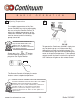
FOR YOUR SAFETY READ BEFORE OPERATING Warning: If you do not follow these instructions exactly, a fire or explosion may result causing property damage, personal injury or loss of life. A. This appliance is equipped with a direct ignition device which automatically lights the burner. Do not try to light the burner by hand. • If you cannot reach your gas supplier, call the fire department. C. Use only your hand to operate remote conB. BEFORE OPERATING: Smell all around trol keypad. Do not use tools.
FOR YOUR SAFETY READ BEFORE OPERATING 7) Turn the manual valve located at the gas inlet of appliance counterclockwise to “ON”. 8) Turn on all electric power to the appliance. 9) Set thermostat to desired setting. 10) If the appliance will not operate, Follow the instructions “To Turn Off Gas To Appliance” and call your service technician or gas supplier. To Turn Off Gas To Appliance 1) Set the thermostat to lowest setting. 2) Turn off all electric power to the appliance if service is to be performed.
Installer’s Instructions This section is for the Rinnai Certified Installer only. If you are not certified you are not authorized to install this unit. The warranty may be voided due to installation by a non-certified installer. For information on becoming a Rinnai Certified Installer, call 1-800-621-9419. Contents of Installer’s Manual Warnings....................................................20 Performance Data..........................................21 Locating the Unit.............................
I N S TA L L E R ’ S I N S TA L L AT I O N I N S T R U C T I O N S -Warnings- This manual must be followed exactly. 1) Read the safety issues completely before installing the Continuum 2424WC. 2) This water heater is suitable for water (potable) heating or space heating. - The piping connected to the Continuum 2424WC must be approved for use in potable water systems. - Toxic chemicals such as those used for boiler water treatment are NOT to be introduced to the Continuum 2424WC.
I N S TA L L E R ’ S I N S TA L L AT I O N I N S T R U C T I O N S C O N T I N U U M O U T L E T F L O W D ATA I N S TA L L E R ’ S I N S TA L L AT I O N I N S T R U C T I O N S C O N T I N U U M P R E S S U R E D R O P C U RV E Model 2424WC 2 1 800-621-9419
I N S TA L L E R ’ S I N S TA L L AT I O N I N S T R U C T I O N S Locating the unit Eve, porche, or overhang C A B Flue C/L Continuum 2424WC D Window Door Vent termination clearances Minimum A.......Vertically below an openable window........................................................12” B.......Vertically above an openable window, door, etc.........................................12” C.......Below eves, porches, overhangs..............................................................36” D......
R E C O M M E N D E D P I P I N G F O R I N S TA L L AT I O N Model 2424WC 23 800-621-9419
INSTALLER’S INSTALLATION INSTRUCTIONS OPTIONAL:Power Failure Freeze Protection www.rinnaiamerica.
INSTALLER’S INSTALLATION INSTRUCTIONS INSTALLATION WITH RECIRCULATION (i.e. Hair Salons, Restaurants, etc.
INSTALLER’S INSTALLATION INSTRUCTIONS BACKUP STORAGE INSTALLATIONS (i.e. Hotels, motels and other high flow applications) www.rinnaiamerica.
I N S TA L L E R ’ S I N S TA L L AT I O N I N S T R U C T I O N S Gas Pipe Sizing Chart Capacity Table for Natural Gas cubic feet / hour (table assumes .3 inch pressure drop, specific gravity of .
I N S TA L L E R ’ S I N S TA L L AT I O N I N S T R U C T I O N S Gas Piping Notes 1) A manual gas control valve must be placed upon the gas inlet connection to the Continuum 2424WC before it is connected to the gas line. A union can be used on the connection of the Continuum for the future servicing or disconnection of the unit. 2) Check the type of gas and the gas inlet pressure before connecting the Continuum 2424WC.
I N S TA L L E R ’ S I N S TA L L AT I O N I N S T R U C T I O N S Water Piping Notes 1) A manual water control valve must be placed upon the water inlet connection to the Continuum 2424WC before it is connected to the water line. Unions may be used on both the hot/cold water supply lines, for the future servicing or disconnection of the unit. 2) All soldering materials and piping must be compatible with potable water. 3) Purge the water line to remove from it all debris and air.
I N S TA L L E R ’ S I N S TA L L AT I O N I N S T R U C T I O N S Electrical Connection Notes WARNING: The Continuum 2424WC must be electrically grounded in accordance with local codes or in the absence of local codes with the most recent edition of the National Electrical Code, ANSI/NFPA 70. In Canada, all electrical wiring to the Continuum 2424WC should be in accordance with local codes and the Canadian Electrical Code, CSA C22.1 Part1.
I N S TA L L E R ’ S I N S TA L L AT I O N I N S T R U C T I O N S Wiring Diagram Model 2424WC 31 800-621-9419
I N S TA L L E R ’ S I N S TA L L AT I O N I N S T R U C T I O N S Wiring Diagram www.rinnaiamerica.
I N S TA L L E R ’ S I N S TA L L AT I O N I N S T R U C T I O N S Lighting the Unit WARNING: If you do not follow these instructions exactly, a fire or explosion may result causing property damage, personal injury or loss of life. 1) This water heater does not have a pilot. It is equipped with a direct ignition device which automatically lights the burner. DO NOT TRY TO LIGHT THE BURNER BY HAND. 2) Before operating the Continuum 2424WC smell all around the unit for gas.
I N S TA L L E R ’ S I N S TA L L AT I O N I N S T R U C T I O N S Remote Controls- General The remote control for the Continuum 2424WC allows the customer to control the functions of the water heater and to diagnose certain fault conditions. The Main Controller model MCC-45-3US is intended to be installed in the kitchen or laundry area where the majority of the hot water is being used. NOTE: The MC-45-3US has a temperature setpoint range of 140-180°F.
INSTALLER’S INSTALLATION INSTRUCTIONS Remote Controls - Installation 1) 2) outline of remote Determine a suitable location for the control. securing screw wire hole (21/32” dia.) Make three holes on the wall as shown. 1 1/16” 3 1/4” securing screw 3) Run the cable between the control and the Continuum 2424WC or the control and the other control. Note: Remote Control Dimensions are: 4 3/4” H x 4 3/4 W” x 1” D 4) Remove the face plate from the remote control, using a screw driver.
I N S TA L L E R ’ S I N S TA L L AT I O N I N S T R U C T I O N S Testing 1) Turn on the gas and water. 2) Check for water and gas leaks. Use soapy water to test for gas leaks. 3) Remove pressure test point screw, attach pressure gauge to test point. 4) Turn Power on. 5) Open any hot water tap fully. 6) Check test point or supply pressure in water columns per inch. Manifold Pressure: Supply pressure: Natural Gas 5.3" Hi. fire 0.43" Lo. fire Natural Gas Min. 7" Max. 10.5" LPG 8.7" Hi. fire 0.
I N S TA L L E R ’ S I N S TA L L AT I O N I N S T R U C T I O N S Diagnostic Points Flow Chart N0 Con N Wire Color 1 J4 2 H1 3 C2 Measurement Point 0 4 Normal Value Component Brown - Blue AC 108 - 132 V Surge Protector Black - Black DC 11 - 13 V Remote Control Red - Black DC 11 - 13 V Yellow - Black DC 2 - 10 V White - Black DC 2 - 9 V Red - Yellow 60 - 350 Hz Yellow - Cabinet Ground AC 100 - 160 V (over DC 1µA) Flame Rod Thermistor Water Flow Sensor D 5 A2 Combustion F
I N S TA L L E R ’ S www.rinnaiamerica.
I N S TA L L E R ’ S Model 2424WC I N S TA L L AT I O N I N S T R U C T I O N S Exploded View - Cabinet 39 800-621-9419
I N S TA L L E R ’ S I N S TA L L AT I O N I N S T R U C T I O N S Exploded View - Internals www.rinnaiamerica.
I N S TA L L E R ’ S I N S TA L L AT I O N I N S T R U C T I O N S Exploded View - Internals Model 2424WC 4 1 800-621-9419
I N S TA L L E R ’ S I N S TA L L AT I O N I N S T R U C T I O N S Exploded View - Electrical www.rinnaiamerica.
I N S TA L L E R ’ S I N S TA L L AT I O N Parts List INSTRUCTIONS Number Description Part Number Quantity 001 Casing Assembly DU195-100-2 1 004 Heat Protection Plate BU155-110 1 007 Front Panel Assembly DU195-1615-2 1 012 Wall Installation Bracket BU195-121 2 016 Front Panel Packing BU195-167 1 017 Front Panel Packing - Side AU115-163 2 018 Connection Reinforcement Panel BU169-120 1 019 Gas Control Bracket BU169-125 1 022 Cable Connection BU56-602-N 1 023 Cable S
I N S TA L L E R ’ S I N S TA L L AT I O N Parts List INSTRUCTIONS Number Description Part Number Quantity 116 Ignition target AU168-325 1 117 Electrode AU168-321 1 118 Flame Rod AU168-322 1 119 Electrode Packing AU195-312 1 120 Electrode Holder AH43-262 1 121 Electrode Sleeve AU102-681 1 125 Heat Exchanger Complete Assy DU-195-1840 1 127 PCB Bracket AU195-330 1 128 Stop Bracket A AU195-321 1 129 Stop Bracket B AU195-322 1 130 Flue Outlet ( Assy) BU169-470 1
I N S TA L L E R ’ S I N S TA L L AT I O N Parts List INSTRUCTIONS Number Description Part Number Quantity 409 Plug Band B AU142-445 1 410 Drain AU142-444 1 415 Modulating Solenoid Valve Harness BU195-601 1 416 Fan Motor Harness BU195-602 1 417 Sensor Harness BU195-1877 1 418 Water Flow Servo Harness BU195-604 1 420 Flame Rod Harness BU195-605 1 700 PCB CU195-1870 1 701 Surge Protector BBF9-630 1 705 PCB Front Cover BU168-707 1 706 PCB Side Cover BU195-507 1
I N S TA L L E R ’ S I N S TA L L AT I O N I N S T R U C T I O N S Parts List Number 801 Description Screw Part Number ZBA041OUK Quantity – 802 Screw ZBA051OUK – 803 Screw ZEAB0408SZ – 804 Screw ZBA0408UK – 805 Screw ZBD0408UK – 806 Screw ZAD0408UK – 807 Screw CP-21478-412 – 808 Screw ZEA0408UK – 809 Screw ZAA0408UK – 810 Screw ZBA0412UK – 811 Screw ZAG0512UK – 812 Screw ZBA0512UK – 816 Screw ZEDB0408SZ – 817 Screw CP-80452 – 819 Screw ZEAB0406UK –
I N S TA L L E R ’ S I N S TA L L AT I O N I N S T R U C T I O N S Parts List Number Description Part Number Quantity 905 “O” Ring (P16) M10B-2-16 1 906 “O” Ring (P12.5) M10B-2-12.
A sk about Rinnai’s other fine products: The Silent Servant *North America’s only vent-free convection heater *99% efficient *whisper quiet *perfect for hard to heat areas The Energy Savers *Direct Vent Heating with style and performance *whisper quiet *available with multi-step set back thermostats The Infra-reds *Vent free radiant heaters *99.9% efficient *Heat like the sun Portable Cooking Products *One, two and two burner with broiler models. *Perfect for camping, a picnic or a tailgate party www.