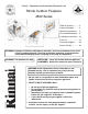
Owner’s Operation and Installation Manual for the Rinnai Outdoor Fireplace 4500 Series Table of Contents ........... 2 Safety Information .......... 2 Operating Instructions .... 8 Care and Maintenance ... 9 Installation Instructions ... 10 Parts List ........................ 21 Consumer Support ......... 26 French Version ............... 28 WARNING: Improper installation, adjustment, alteration, service or maintenance can cause injury or property damage.
Table of Contents Consumer Safety Information Safety Definitions ........................................ 2 Safety Behaviors and Practices .................. 3 Safety Features ........................................... 3 Specifications ................................................. 4 Troubleshooting ......................................... 4 Dimensions ................................................. 5 Assembly Specifications ............................. 6 Installation Applications ..................
Safety Behavior and Practices WARNING • Keep the area around the appliance clear and free from combustible materials, gasoline, and other flammable vapors and liquids. • Do not use this appliance if any part has been under water. Immediately call a qualified service technician to inspect the appliance and to replace any part of the control system and any gas control which has been under water. • Installation and servicing should be performed by a licensed or qualified service technician.
Specifications Application As a permanently fixed heating appliance in outdoor areas only. Complies with CSA International Requirement 4.96 U.S. for Outdoor Gas Fireplaces. General Description Open fronted radiant/convector outdoor gas fireplace with manual control.
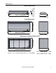
Dimensions 42.52 in (1080 mm) 4.76 in 3.00 in (121 mm) (76 mm) Burner Dimensions 15.75 in (400 mm) 21.65 in (550 mm) Body Dimensions 46.06 in (1170 mm) 23.03 (585) 18.50 in (470 mm) With Fascia and Doors Dimensions 47.44 in (1205 mm) 19.21 in (488 mm) for 1-sided Frame is 1.57 in (40 mm) wide, 0.67 in (17 mm) deep Rinnai Corporation ROF4500 19.
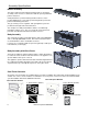
Assembly Specifications Burner Assembly The major component of the Rinnai outdoor fireplace is the burner assembly. This consists of a tube burner with an open tray filled with pumice and stones. A SIT pilot burner is positioned along the tube burner to ensure positive lighting and is covered by a perforated guard to prevent the pumice from blocking the burner. The gas control, pressure regulator, and spark ignition system are positioned at the right end of the tube burner.
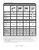
Installation Applications Sample Installations Components Needed Freestanding (ROF4500) Open 1-Sided Cabinet (ROF4501) Open 2-Sided Cabinet (ROF4502) Non-combustible enclosed masonry Burner Assembly LPG (ROF4500) OR 1-Sided Burner/Body Assembly LPG (ROF4501) [1] OR 2-Sided Burner/Body Assembly LPG (ROF4502) [1] Optional Accessories Glass Bi-fold Door Assembly (R2612) [2] [3] LPG-NG Conversion Kit (R2613) (included with appliance and available for purchase) Console Door Module (R2631) Console Base
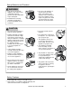
Operating Instructions Before Starting the Appliance • Remove the weather cover. • Inspect the burner before each use of the appliance. Ensure that no debris such as leaves or other objects have entered or are on the appliance. If the burner is damaged, it must be replaced with a Rinnai authorized replacement burner prior to operating the appliance. • Completely open the door (if present). • Inspect the gas supply hose before each use of the appliance.
Maintenance For safe operation of the appliance it is imperative that the control compartment (pilot cover), burner and circulating air passageways are kept clean. To keep the gas orifices from getting clogged, ensure that debris is kept clear from the fire, and that the burn media is installed correctly. The appliance should be inspected before use and at least annually by a qualified service technician. More frequent cleaning may be required. Regular servicing is not covered by Rinnai’s warranty.
Installation Instructions General Instructions WARNING Do not use substitute materials. Use only parts certified with the appliance. A qualified service technician should install the appliance and inspect it before use. The installation must conform with local codes or, in the absence of local codes, with the National Fuel Gas Code, ANSI Z223.1.
LPG Cylinder Enclosure Enclosures for LP-gas supply cylinders shall be ventilated by openings at the level of the cylinder valve and at floor level. This shall be accomplished by one of the following: A. One side of the enclosure shall be completely open; or B. For an enclosure having four sides, a top and a bottom: 1. At least two ventilation openings at cylinder valve level shall be provided in the side wall, equally sized, spaced at 180 degrees, and unobstructed.
Definition of an Outdoor Area This appliance shall only be used in an above ground open air situation with natural ventilation, without stagnant areas, where gas leakage and products of combustion are rapidly dispersed by wind and natural convection. Any enclosure in which the appliance is used shall comply with one of the following: NOTICE The clearances on the next page must be followed. • With walls on all sides, but at least one permanent opening at ground level and no overhead cover.
Clearances Body Assembly (open 1 sided or 2 sided) Freestanding recommended Description Clearance Required Additional Detail (A) Below eaves, balconies, or other projections 39.37 in (1000 mm) If the projection is a shade cloth or material awning then this is deemed as a combustible material and the recommended clearance is 59.05 in (1500 mm). (B) From the ground or 3.94 in (100 mm) cabinet other surface Recommended 27.6 in (700 mm) freestanding Ground level to bottom of fireplace.
Installing Freestanding or Enclosed Masonry Applications Prepare Surround Construct surround following the clearances to combustibles and minimum height from ground. The surround must be a permanent and fixed construction. Non-combustible Enclosed Masonry Freestanding recommended Minimum Dimensions A 21.85 in (555 mm) B 46.26 in (1175 mm) C 18.50 in (470 mm) Prepare a gas connection opening underneath the gas supply access position.
Installing Body Assembly in an Open 1-Sided or 2-Sided Installation Steel framing options are available for the open 1-sided and open 2-sided installations. For ease of installation, Rinnai provides a steel frame as a kit. Refer to the separate detailed instructions for assembly of the steel frame. To enhance the durability of any type of framing, it is suggested that the frame is mounted on a paved slab 9.5 inches (250 mm) above unpaved ground and 5.9 inches (150 mm) above paved ground.
Installing Body Assembly in an Open 1-Sided or 2-Sided Installation Angled Clearance Brackets Designed to ensure combustible framing is greater than 1 inch (25 mm) from the sides of the unit as shown. 48.3 in (1225 mm) minimum Top View Open 1-sided Cabinet timber stud cabinet clearance bracket Top View 19.7 in non combustible (500 mm) cladding minimum 46.5 in (1180 mm) minimum 47.0 in (1195 mm) maximum timber stud 48.
Installing Body Assembly in an Open 1-Sided or 2-Sided Installation Install Doors if Applicable Refer to separate installation instructions. Install Body Assembly into Frame The body assembly includes the burner assembly. Unpack and fit assembly into frame using the mounting brackets. For an open 2-sided installation, ensure the control knob is facing in the desired direction.
Installing Burn Media WARNING Proper installation of the burn media is critical to the correct operation of this appliance. Each layer must be installed as specified below. If using the optional fireglass or driftwood burn media, installation instructions are included with those accessories. Layer 1 - Pumice Use a scoop or gloved hands to transfer the pumice. Avoid pouring because dust particles can clog the burner. Fill the burner tray with pumice and spread level to the bottom of the granite trims.
Complete Gas Connection LPG Cylinder The installer/consumer must supply a certified regulator and hose assembly with a 3/8 SAE 45º flare fitting with 5/8 UNF thread. These parts and their installation must conform with local codes or, in the absence of local codes, with the National Fuel Gas Code, ANSI Z223.1/NFPA 54, or the Natural Gas and Propane Installation Code, CSA B149.1. The cylinder to be used must be constructed and marked in accordance with the specifications for LPG cylinders of the U.S.
Guidelines for Cladding and Finishes These are guidelines only. It is up to the installer to seek advice from the cladding supplier as to the correct application and specification of the material. All materials and finishes directly above the appliance must be capable of withstanding the following temperatures: • with the door assembly installed 302° F (150° C) • without the door assembly installed 212° F (100° C) Cladding materials shall be non-combustible and suitable for an outdoor environment.
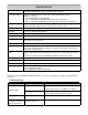
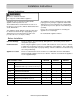
Parts List Item No. QTY Part No. Description Item No. QTY Part No.
Parts List Item No. QTY Part No. Description Item No. QTY Part No.
Parts List Quantity Item No. Part No.
Parts List Item No. Quantity Part No. Description 1 1 11264 FASCIA TOP 2 1 11266 FASCIA BOTTOM 3 2 11265 FASCIA VERTICAL 4 8 9065 SCREW M4x10 PAN PHIL ST.ST 304 The complete assembly can be purchased as Kit R2615 Frame Trim SS.
Parts List Item No. Quantity Part No.
Consumer Support Warranty Information The installer is responsible for your heater’s correct installation. Please complete the information below to keep for your records: Purchased from: ___________________________________________________________ Address: _____________________________ Phone: ___________________________ _____________________________ Date of Purchase: __________________________________ Model No.: ________________________________________ Serial No.
Limited Warranty - continued Replacement of the product may be authorized by Rinnai only. Rinnai does not authorize any person or company to assume for it any obligation or liability in connection with the replacement of the product. If Rinnai determines that repair of a product is not possible, Rinnai will replace the product with a comparable product at Rinnai’s discretion.
Manuel de l'opération et de l'installation du propriétaire pour Rinnai Cheminée Extérieur 4500 Series Table des matières ........ 29 Informations de sécurité . 29 Instructions d'utilisation .. 35 Entretien ....................... 36 Instructions d'installation 37 Liste de pièces ............... 21 Support à clientèle ......... 48 AVERTISSEMENT: L'installation inexacte, l'ajustement, le changement, le service ou l'entretien peuvent causer des dommages ou des dégats matériels.
Table des matières Informations pour la sécurité du consommateur Définitions de sécurité ............................... 29 Comportements et pratiques de sécurité .. 30 Dispositifs de sécurité ............................... 30 Spécifications ............................................... 31 Dépannage ............................................... 31 Dimensions................................................ 32 Caractéristiques d'Assemblée ................... 33 Applications d'installation ...............
Comportements et pratiques de sécurité AVERTISSEMENT • Gardez la zone autour de l’appareil dégagée et exempte de matériaux combustibles, essence et autres vapeurs et liquides inflammables. N’utilisez pas cet appareil s’il a été plongé dans l’eau, même partiellement. Faites inspecter l’appareil par un technicien qualifié et remplacez toute partie du système de contrôle et toute commande qui ont été plongés dans l’eau.
Spécifications Application Comme appareil de chauffage de manière permanente fixe dans des secteurs extérieurs seulement. Se conforme à la condition internationale 4.96 États-Unis de CSA pour les cheminées extérieures de gaz. Description générale Ouvrez la cheminée extérieure affrontée de gaz d'élément chauffant/convecteur avec la commande manuelle.
Dimensions 42.52 in (1080 mm) 4.76 in 3.00 in (121 mm) (76 mm) Burner de Dimensions Dimensions brûleur 15.75 in (400 mm) 21.65 in (550 mm) Dimensions de corps Body Dimensions 46.06 in (1170 mm) 23.03 (585) 18.50 in (470 mm) Withdes Fascia and Doors Dimensions Avec Aimensions de Fasce et de Porte 47.44 in (1205 mm) 19.21 (488) mm) pour 1for dégrossi 19.21 in (488 1-sided La vue est 15.7 loin,wide, 0.67 (17) profondément Frame is 1.57 in (40) (40 au mm) 0.
Caractéristiques d'Assemblée Assemblée de brûleur Le composant principal de la cheminée extérieure de Rinnai est le brûleur. Ceci se compose d'un brûleur à tube avec un plateau ouvert rempli de rénovation et de pierres. Un brûleur de pilote de SIT est placé le long du brûleur à tube pour assurer l'éclairage positif et est couvert par une garde perforée pour empêcher la rénovation de bloquer le brûleur.
Applications d'installation Installations témoin Les composants ont eu Libre (ROF4500) besoin 1 a dégrossi (ROF4501) 2 dégrossis (ROF4502) Maçonnerie incluse non-combustible Assemblée de brûleur LPG (ROF4500) OR 1 a dégrossi Assemblée de brûleur [1] LPG (ROF4501) OR 2 dégrossis Assemblée de brûleur LPG (ROF4502) [1] Accessoires facultatifs De verre Bi-pliez l'Assemblée de porte (R2612) [2] [3] LPG-NG Kit de conversion (R2613) (inclus avec l'appareil et disponible pour l'achat) Module de porte (R
Instructions d'utilisation Avant de commencer l'appareil • Enlevez la couverture de temps. • Inspectez le brûleur avant chaque utilisation de l'appareil. Assurez-vous qu'aucun débris tel que des feuilles ou d'autres objets ne sont entrés ou sont sur l'appareil. Si le brûleur est endommagé, il doit être remplacé avec un brûleur autorisé par Rinnai de rechange avant d'actionner l'appareil. • Ouvrez complètement la porte (si présent).
Entretien Pour l'exploitation sûre de l'appareil il est impératif que le compartiment de commande (couverture pilote), le brûleur et les passages de circulation d'air soient maintenus propres. Pour garder les orifices de gaz d'obtenir obstrué, assurez-vous que des débris sont gardés clairement du feu, et que les médias de brûlure est installés correctement. L'appareil devrait être inspecté avant emploi et au moins annuellement par un technicien qualifié de service.
Instructions d’installation Avant d’installation AVERTISSEMENT N'employez pas les matériaux de remplacement. Employez seulement les pièces certifiées avec l'appareil. Un technicien qualifié de service devrait installer l'appareil et l'inspecter avant emploi. L'installation doit se conformer aux codes locaux ou, en l'absence des codes locaux, au code national de gaz de carburant, la norme ANSI Z223.1.
Clôture de cylindre de LPG Des clôtures pour des cylindres d'offre de LP-gaz seront aérées par des ouvertures au niveau de la valve de cylindre et au niveau de plancher. Ceci sera accompli par un du suivant: A. Un côté de la clôture sera complètement ouvert ; ou 1. Pour une clôture ayant quatre côtés, un dessus et un bas: 2. Au moins deux ouvertures de ventilation au niveau de valve de cylindre seront fournies dans le mur latéral, également classé, espacé à 180 degrés, et dégagé.
Définition d'un secteur extérieur Cet appareil sera seulement employé dans une situation en plein air au sol ci-dessus avec la ventilation normale, sans secteurs stagnants, où la fuite de gaz et les produits de la combustion sont rapidement dispersés par le vent et la convection normale. N'importe quelle clôture dans laquelle l'appareil est employé sera conforme à un de ce qui suit : NOTICE • Les dégagements à la prochaine page doivent être suivis.
Espacements Assemblée de corps (ouvrez 1 dégrossi ou 2 dégrossis) Libre Recommandé minimum de la terre Description Espacements requis Information supplémentaire (A) Au-dessous des gouttières, des balcons, ou d'autres projections 39.37 in (1000 mm) Si la projection est une tente de tissu ou de matériel d'ombre puis ceci est considéré comme matériel combustible et le dégagement recommandé es 59.05 in (1500 mm). (B) De la terre ou de toute autre surface 3.
Installation de l'unité indépendante oumaçonnerie incluse Préparez la bordure La construction entourent suivre les dégagements aux combustibles et la taille minimum de la terre. L'entourage doit être une construction permanente et fixe. Maçonnerie incluse non-combustible Libre Recommandé minimum de la terre Dimensions Minimum A 21.85 in (555 mm) B 46.26 in (1175 mm) C 18.50 in (470 mm) Préparez une ouverture de raccordement de gaz sous la position d'accès d'offre de gaz.
L'installation du montage de corps dans un 1 ouvert a dégrossi ou 2 ont dégrossi installation Les options encadrantes d'acier sont disponibles pour le 1 ouvert dégrossi et ouvrent 2 installations dégrossies. Pour la facilité de l'installation, Rinnai fournit une armature en acier comme kit. Référez-vous aux instructions détaillées séparées pour l'ensemble de l'armature en acier. Pour augmenter la longévité de n'importe quel type d'encadrer, on le suggère que l'armature soit montée sur une galette pavée 9.
L'installation du montage de corps dans un 1 ouvert a dégrossi ou 2 ont dégrossi installation A conçu pour assurer encadrer combustible est 1 pouce plus grand que (25 millimètres) des côtés de l'unité comme montrés. Équerres 48.3 in (1225 mm) minimum vue aérienne Ouvrez 1 Cabinet dégrossi timber stud faisceau en bois coffret cabinet revêtement non 19.
L'installation du montage de corps dans un 1 ouvert a dégrossi ou 2 ont dégrossi installation Installez les portes si c'est approprié Référez-vous aux instructions d'installation séparées. Installez le montage de corps sur l'armature Le corps inclut le brûleur. Déballez, et adaptez l'assemblée dans l'armature à l'aide des supports. Pour des 2 ouverts dégrossis l'installation, assurent le bouton de commande est des revêtements dans la direction désirée.
Installation des médias de brûlure AVERTISSEMENT L'installation appropriée des médias de brûlure est critique à l'opération correcte de cet appareil. Chaque couche doit être installée comme indiqué ci-dessous. Si en utilisant les fireglass ou les médias facultatifs de brûlure de bois de flottage, des instructions d'installation sont incluses avec ces accessoires. Couche 1 - Ponce Utilisez un godet ou des mains enfilées de gants pour transférer la ponce.
Accomplissez le raccordement de gaz Cylindre—gas de propane liquide L'installateur/consommateur doit fournir un ensemble certifié de régulateur et de tuyau un ajustage de précision de fusée de 3/8 SAE 45º avec 5/8 fil d'UNF. Ces pièces et leur installation doivent se conformer aux codes locaux ou, en l'absence des codes locaux, au code national de gaz de carburant, à la norme ANSI Z223.1/NFPA 54, ou au code d'installation de gaz naturel et de propane, CSA B149.1.
Directives pour le revêtement et les finitions Ce sont des directives seulement. Il appartient à l'installateur pour chercher le conseil du fournisseur de revêtement quant à l'application et aux spécifications correctes du matériel.
Support à la clientèle L'information de garantie L'installateur est responsable de l'installation correcte de votre réchauffeur. Veuillez remplir l'information ci-dessous pour garder pour vos disques : Acheté de: ___________________________________________________________ Adresse: _____________________________ Téléphone: ___________________________ _____________________________ Date d'achat: __________________________________ Numéro de type:________________________________________ Numéro de série.
Garantie limitée Le remplacement du produit ne peut être autorisé que par Rinnai. La société Rinnai ne permet à aucune personne ou société d’assumer pour elle toute obligation ou responsabilité relative au remplacement d’un produit. Si Rinnai détermine que la réparation d’un produit n’est pas possible, Rinnai le remplacera avec un produit comparable, à sa discrétion.
Notes 50 Rinnai Corporation ROF4500
Notes Rinnai Corporation ROF4500 51
Rinnai’s other fine products For information on Rinnai’s products contact Rinnai America Corporation 103 International Drive Peachtree City, GA 30269 TOLL FREE: 1-800-621-9419 FAX: 678-829-1666 www.rinnai.us Tankless Water Heaters • • • • • • • • Residential and Commercial Applications Continuous Hot Water Up to 9.