
Installation Sheet


Fan Convector Manual 9
High Altude Installaons
1. Turn o gas and power supply to unit.
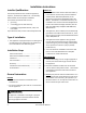
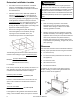
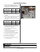
2. Remove 7 screws securing front panel. (FIGURE 1)
3. Remove front panel.
4. Turn on power to the unit.
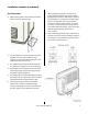
5. Locate the test switch at the top of the PC Board.
(FIGURE 2)
6. Press and hold the Test Switch for 1-2 seconds. The
display will now display the current gas type and
altude seng (see chart below).
7. Using the “UP”(▲) and the “DOWN” (▼) buons
select the appropriate gas type and altude
range for the applicaon.
8. Once the selecon has been made and is displayed
on the LED, press the Test Switch 3 mes unl the
unit is in the normal o seng.
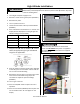
9. Remove the test port plug on the gas control valve
and connect a manometer using a 1/8” test
connecon to adjust the pressure sengs.
(FIGURE 3)
10. Turn on gas to the unit.
11. Press the “ON/OFF” buon to place the unit in
operaon.
12. Press the Test switch (FIGURE 2) twice to place the
unit in Low re mode. “PL” will appear on the
display.
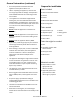
Gas posion Gas type Altude ()
13 NG 0-2000
14 NG 2001-5200
L1 LP 0-2000
L2 LP 2001-5200
FIGURE 1
The following procedure for high altude installaons above 2,000 feet must be
performed by a licensed professional. Failure to perform this adjustment may result
in the unit shung down.
ATTENTION
CAUTION
Do not touch any other areas on the PC board
besides the Test Switch while power is supplied to
the appliance. Parts of the PC board are supplied
with 120 volts AC.
Test
Switch
FIGURE 2