
Installation Sheet


Installation & Servicing Instructions Rinnai E-Series
44
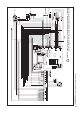
Connection terminal gure 22
NOTICE
i
The Rinnai room thermostat and controls must be connected to their allocated
connections. All other types or makes of room thermostats or controls which
are used must have a Volt free contact.
When using an on/o thermostat or control, it may be necessary to calibrate the
anticipatingresistancetopreventtoohightemperatureuctuations.Asastandard
rule this means mercury thermostats. This resistance wire is present in the Control
Tower and must be connected to terminals 23 and 27. The anticipating resistance in
the room thermostat has to be set at 0.11 A.
For more detailed questions regarding the components which are not supplied, the
distributor should be contacted.
When wiring an RS100 it is suggested that a jumper be placed on terminals 22
and 23 so that in the event the control is damaged the boiler will still re based
on outdoor reset.
A jumper should also be used when commissioning or trouble shooting the
boiler.
Power stealing thermostats cannot be connected to terminals 22 and 23.
NOTICE
i
NOTICE
i
Connection terminal E-Series
!
CAUTION
120 V~
10
11
120 V~ 120 V~ 120 V~
Power supply
Cylinder connection
8U.35.60.00
Outside
sensor
Bus
Controller
24 V~
100 mA
1 2 3 4 5 6 7 8 9 12 13 14 15 16 17
18
19 20 21
22
23 24 25 26 27
N LN L N L N L
CH
DHW N A B
DHW
sensor
three-way valve
Room
therm.
On / Off
External
safety
contact
main power supply
120 Volts
Rinnai only
120 Volts
Rinnai only
internal or external
three-way valve motor
and
tank sensor
Bus room thermostat
RS100
On/othermostator
control (Volt free)
ARV12 outdoor sensor
External safety contact
120 Volts for external
pump
CAUTION
Make sure that the power consumption of each of the terminals 4-5-6 does not
exceed 230W or 2 Amp.
CAUTION
Terminals 7 to 11 are for Rinnai use only and not for use in any installation.
!
CAUTION