
Installation Sheet


Installation & Servicing Instructions Rinnai E-Series
34
Terminals should be positioned as to avoid products of combustion entering
openings into buildings or other vents.
Maintain 12” of clearance above the highest anticipated snow level or grade
or, whichever is greater. Please refer to your local codes for the snow level in
your area.
The termination shall be at least 4 feet (1,220 mm) distance from electric meters,
gas meters, regulators and relief equipment. (for room air application only)
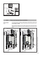
Horizontal vent systems should always be installed sloping towards the boiler
(min. 21 mm/m, 1/4”/ feet), in order to avoid condensate retaining in the vent
system. With the condensate running back to the boiler the risk of ice forming
at the terminal is reduced.
The whole route of the exhaust vent system must be installed upwards, never
downwards, completely nor partly.
Place pipe supports every 4 feet (1219 mm) of horizontal run, beginning with
the support near the boiler to prevent movement in ttings and allow boiler to
be free from any strain or weight on boiler or ttings.
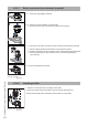
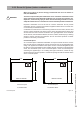
The terminal should be located where dispersal of combustion products is not
impeded and with due regard for the damage or discoloration that might occur
to building products or vegetation in the vicinity (see g 15 and 16).
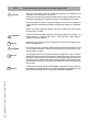
In certain weather conditions condensation may also accumulate on the outside
of the air inlet pipe. Such conditions must be considered and where necessary
insulation of the inlet pipe may be required.
In cold and/or humid weather water vapor may condense on leaving the vent
terminal. The eect of such ‘water condensation’ must be considered. The
terminal must be located in a place not likely to cause a nuisance.
Cellular or Foam core PVC, CPVC and Radel is not permitted for use with the
boiler.
The application of any type of insulation is prohibited for use with any Plastic
venting system.
NOTICE
i
!
CAUTION
!
CAUTION
NOTICE
i
NOTICE
i
NOTICE
i
NOTICE
i
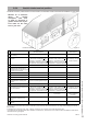
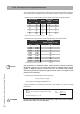
Approval codes for installation of venting system table 7
NOTICE
i
Item Description Flue Material United States
PVC Schedule 40 ANSI/ASTM D1785
PVC - DWV ANSI/ASTM D2665
CPVC Schedule 40 ANSI/ASTM F441
PVC ANSI/ASTM D2564
CPVC
A
NSI/ASTM F493
Item Description Flue Material Manufacturer Approval code
US/CAN
Flue system
Stainless steel vent systems Stainless Steel Ubbink
Rolux Condensing
Vent System
Plastic Vent System PP Ubbink ULC S636
Rolux Condensing
Vent System
Plastic Vent System PVC/CPVC Various ULC S636 System 636
Plastic Vent System PPS Centrotherm ULC S636 and UL 1738 Innoflue
Plastic Vent System PP Dura-Vent ULC S636 Poly Pro & Poly Pro Flex
Approval Codes for Installation
Canada
Plastic Vent and/or air pipes and
fittings
ULC S636
Plastic Pipe cement and primer
Saf-T Vent SC
Saf-T Vent EZ Seal
Stainless steel vent systems Stainless Steel Heat Fab
UL1738 Concentric
twin pipe
Stainless steel vent systems Stainless Steel Simpson Dura-Vent
FastNSeal Flex
FastNSeal
UL1738 Flexible liner
UL1738 Concentric
twin pipe
NOTICE
i
NOTICE
i