Guaranty and Declaration Copyright © 2022 RIGOL TECHNOLOGIES CO., LTD. All Rights Reserved. Trademark Information RIGOL®is the trademark of RIGOL TECHNOLOGIES CO., LTD. Software Version Software upgrade might change or add product features. Please acquire the latest software version from RIGOL website or contact RIGOL to upgrade the software. Notices • RIGOL products are covered by P.R.C. and foreign patents, issued and pending.
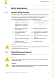
Safety Requirement 1 Safety Requirement 1.1 General Safety Summary Please review the following safety precautions carefully before putting the instrument into operation so as to avoid any personal injury or damage to the instrument and any product connected to it. To prevent potential hazards, please follow the instructions specified in this manual to use the instrument properly. 1 Only the exclusive power cord 9 designed for the instrument and Do not operate the instrument with suspected failures.
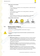
Safety Requirement Safety Notices on the Product: • DANGER It calls attention to an operation, if not correctly performed, could result in injury or hazard immediately. • WARNING It calls attention to an operation, if not correctly performed, could result in potential injury or hazard. • CAUTION It calls attention to an operation, if not correctly performed, could result in damage to the product or other devices connected to the product. Safety Symbols on the Product: 1.
Safety Requirement equipment. For example, stationary motors with permanent connection to a fixed installation. • Measurement category IV is for measurements performed at the source of a low-voltage installation. Examples are electricity meters and measurements on primary overcurrent protection devices and ripple control units. 1.4 Ventilation Requirement This instrument uses a fan to force cooling. Please make sure that the air inlet and outlet areas are free from obstructions and have free air.
Safety Requirement Protection Level Against Electric Shock ESD ±8kV Installation (Overvoltage) Category This product is powered by mains conforming to installation (overvoltage) category II. WARNING Ensure that no overvoltage (such as that caused by a bolt of lightning) can reach the product. Otherwise, the operator might be exposed to the danger of an electric shock.
Safety Requirement Cleaning Clean the instrument regularly according to its operating conditions. 1. Disconnect the instrument from all power sources. 2. Clean the external surfaces of the instrument with a soft cloth dampened with mild detergent or water. Avoid having any water or other objects into the chassis via the heat dissipation hole. When cleaning the LCD, take care to avoid scarifying it. CAUTION To avoid damage to the instrument, do not expose it to caustic liquids.
Document Overview 2 Document Overview This manual gives you a quick overview of the front and rear panel, user interface as well as basic operation methods of DHO1000 series. TIP For the newest version of this manual, download it from RIGOL official website (http:// www.rigol.com). Publication Number QGA32103-1110 Software Version Software upgrade might change or add product features. Please acquire the latest version of the manual from RIGOL website or contact RIGOL to upgrade the software.
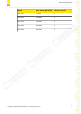
Document Overview Model Max. Analog Bandwidth Analog Channels DHO1074 70 MHz 4 DHO1102 100 MHz 2 DHO1104 100 MHz 4 DHO1202 200 MHz 2 DHO1204 200 MHz 4 Copyright ©RIGOL TECHNOLOGIES CO., LTD. All rights reserved.
General Inspection 3 General Inspection 1. Inspect the packaging If the packaging has been damaged, do not dispose the damaged packaging or cushioning materials until the shipment has been checked for completeness and has passed both electrical and mechanical tests. The consigner or carrier shall be liable for the damage to the instrument resulting from shipment. RIGOL would not be responsible for free maintenance/rework or replacement of the instrument. 2.
Product Overview 4 Product Overview DHO1000 series digital oscilloscope is designed to meet the requirements for the design, debug, and test of the mainstream oscilloscope market.
Product Overview 2 1 3 4 56 7 8 9 10 11 12 15 13 14 Figure 4.2 Front Panel (2-channel Model) 1 10.
Product Overview 4.2 Rear Panel Overview 5 6 7 4 3 2 8 9 1 10 Figure 4.3 Rear Panel 1 Trigger Output Connector 2 External Trigger Input Connector 3 10 MHz Reference Clock Input Connector 4 10 MHz Reference Clock Output Connector 5 HDMI Connector 6 USB DEVICE Port 7 LAN Port 8 AC Power Cord Connector 9 Fuse 10 Security Lock Hole Copyright ©RIGOL TECHNOLOGIES CO., LTD. All rights reserved.
Product Overview 4.3 User Interface Overview Figure 4.4 User Interface 1 Waveform View 8 Result Sidebar 2 Run State Label 9 Notification Area 3 Horizontal Timebase Label 10 Split-screen Display 4 Sample Rate & Memory Depth 11 Math Labels 5 Horizontal Delay Label 12 Channel Labels 6 Trigger Label 13 Function Navigation Icon 7 Function Toolbar Label 12 Copyright ©RIGOL TECHNOLOGIES CO., LTD. All rights reserved.
To Prepare for Use 5 To Prepare for Use 5.1 Tilting the Oscilloscope for Easier Viewing Flip out the tabs under the oscilloscope's rear feet to tilt the oscilloscope to stabilize it for easier operation and viewing. Flip in the tabs for storage or transporting when not using the instrument. Please see the figure below. Figure 5.1 Flipping in/out Tabs 5.2 Connecting to Power The power requirements of the oscilloscope are 100-240 V, 50-60 Hz.
To Prepare for Use Figure 5.2 Connecting to Power WARNING To avoid electric shock, ensure that the instrument is correctly grounded. 5.3 Turn-on Checkout After the instrument is connected to the power source, press the power switch at the lower-left corner of the front panel to power on the instrument. During the startup process, the instrument performs a series of self-tests. After the self-test, the splash screen is displayed. • Restart: Click or tap > Restart.
To Prepare for Use TIP You can also click or tap > Utility > Setup and select "Switch On" in "Power Status" item. In this way, the instrument powers on once connected to power. 5.4 Setting the System Language This oscilloscope supports multiple languages. You can click or tap > Utility > Setup > Language to select the system language. 5.5 Connecting Probes RIGOL provides passive probes for DHO1000 series. For specific probe models, please refer to DHO1000 series Data Sheet.
To Prepare for Use 5.6 Function Inspection 1. Press the front-panel and a prompt message "Restore default settings?" is displayed. Click or tap OK to restore the instrument to its factory default settings. 2. Connect the ground alligator clip of the probe to the "Ground Terminal" as shown in Figure 5.4 . 3. Use the probe to connect the input terminal of CH1 and the "Compensation Signal Output Terminal" of the probe, as shown in Figure 5.4 . Figure 5.4 Using the Compensation Signal 4.
To Prepare for Use 6. Test the other channels in the same way. If you see the waveform, but the square wave is not shaped correctly as shown above, perform the procedure described in Probe Compensation. If you do not see the waveform, perform these steps again. WARNING To avoid electric shock when using the probe, please make sure that the insulated wire of the probe is in good condition. Do not touch the metallic part of the probe when the probe is connected to high voltage source. 5.
Touch Screen Gestures 6 Touch Screen Gestures The instrument's large capacitive touch screen makes operation and configuration easy and flexible. The highly sensitive user interface designed for touch has a strong waveform display capability, bringing an extraordinary user experience. The actions supported by the touch screen controls include tapping, pinching&stretching, as well as dragging. 6.1 Tap Use one finger to tap the symbol or characters on the screen slightly, as shown in Figure 6.1 .
Touch Screen Gestures • Drag the waveform to change its position or scale. • Drag the window controls to change the position of the window (e.g. numeric keypad). • Drag the cursor to move the cursor. • Drag the trigger cursor to change the trigger level. • In multi-window display, drag one of the displayed windows to change its position on the display. Figure 6.2 Drag Gesture 6.3 Pinch&Stretch Pinch or stretch two points on the screen with two fingers to zoom in or out the waveform.
Touch Screen Gestures Figure 6.3 Pinch&Stretch Gesture 20 Copyright ©RIGOL TECHNOLOGIES CO., LTD. All rights reserved.
Accessing the Built-in Help System 7 Accessing the Built-in Help System The built-in help system provides instructions for all the front-panel keys and their corresponding menu keys. Click or tap > Help to access the "Help" menu. After that, you can get its help information by clicking on or tapping the link for the desired item. Copyright ©RIGOL TECHNOLOGIES CO., LTD. All rights reserved.
Parameter Setting Method 8 Parameter Setting Method For this instrument, you can use the knobs and touch screen to set parameters. The common parameter setting methods are as follows: • Method 1: Some parameters can be adjusted by rotating the front-panel knobs. • Method 2: Click or tap the input field of a specified parameter, then a virtual keypad is displayed. Complete the parameter setting with the keypad.
Parameter Setting Method • Set the parameter value to a maximum or minimum value; • Set the parameter to a default value. • Clear the parameter input field. Copyright ©RIGOL TECHNOLOGIES CO., LTD. All rights reserved.
Replacing the Fuse 9 Replacing the Fuse If you need to replace the fuse, please use the correct fuse (AC 250 V, T3.15 A; 5.2 mm×20 mm) and follow the steps shown below (see Figure 9.1 ). 1. Power off the instrument and remove the power cord. 2. Insert a small straight screwdriver into the slot at the power socket and pry out the fuse holder gently. 3. Remove the fuse. 4. Insert the proper fuse into the fuse holder. 5. Re-insert the fuse holder into the power socket. Figure 9.
Remote Control 10 Remote Control The instrument can be remotely controlled by the following three methods: • User-defined Programming Users can program and control the instrument by using the SCPI (Standard Commands for Programmable Instruments) commands. For details about the SCPI commands and programming, refer to Programming Guide. • PC Software Users can use the PC software to send commands to control the instrument remotely. RIGOL Ultra Sigma is recommended.
More Product Information 11 More Product Information 1. Obtain the Device Information Click or tap > Utility > About to obtain the information of the instrument, such as the model, serial number, and firmware version number. 2. View the Option Information and Install the Option The instrument is installed with the trial versions of the options before leaving factory. The trial time starts from the time when you power on the instrument for the first time, and the trial time is about 2,160 minutes.