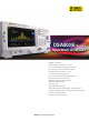
DSA800/E Series Spectrum Analyzer ● All-Digital IF Technology ● Frequency Range from 9 kHz up to 7.5 GHz ● Min. -161 dBm Displayed Average Noise Level (Typ.) ● Min. < -98 dBc/Hz @ 10 kHz Offset Phase Noise ● Level Measurement Uncertainty < 0.8 dB ● 10 Hz Minimum Resolution Bandwidth ● Up to 7.5 GHz Tracking Generator (DSA8XX/E-TG) ● Advanced Measurement Functions (Opt.) ● EMI Filter & Quasi-Peak Detector Kit (Opt.) ● VSWR Measurement Kit (Opt.) ● PC Software (Opt.
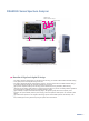
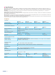
DSA800/E Series Spectrum Analyzer Advanced Measurement Keys Basic Keys USB Port TG Output Marker Keys RF Input Product Dimensions: Width X Height X Depth = 361.6 mm x 178.8 mm x 128 mm Benefits of Rigol's all digital IF design The ability to measure smaller signals: on the basis of this technology, the IF filter enables smaller bandwidth settings, which greatly reduce the displayed average noise level.
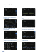
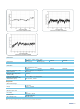
Features and Benefits Distinguish the two nearby signals clearly with the 10 Hz RBW Compare the spectrums with different color trace Readout the spectrum peak values with the peak table function Measure lower level signal with the preamplifier turn on Phase noise < -98 dBc/Hz @10 kHz offset (DSA832/875/832E) EMI kit (EMI filter & Quasi-peak & Pass/Fail) The GUI to control the RF demo kit (Transmitter) directly RIGOL 3 VSWR measurement
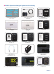
RIGOL Spectrum Analyzer Option and Accessory Harmonic Distoration TOI Occupied Bandwidth Channel Power Time Domain Power Emission Bandwidth Carrier to Noise Ratio Adjacent Channel Power Pass/Fail Advanced Measurement Kit (AMK-DSA800) RF Demo Kit ( TX1000 ) USB to GPIB Converter ( USB-GPIB ) RF Demo Kit ( RX1000 ) VSWR Bridge ( VB1032/VB1040/VB1080 ) RF CATV Kit DSA Utility Kit RF Adaptor Kit RF Attenuator Kit RF Cable Kit High Power Attenuator ( ATT03301H ) DSA PC Software ( Ultra Spectru
Specifications Specifications are valid under the following conditions: the instrument is within the calibration period, is stored for at least two hours at 0 ℃ to 50 ℃ temperature, and is warmed up for 40 minutes. Unless otherwise noted, the specifications in this manual include the measurement uncertainty. Typical (typ.): characteristic performance, which 80 percent of the measurement results will meet at room temperature (approximately 25℃ ).
Residual FM Residual FM 20℃ to 30℃ , RBW = VBW = 1 kHz DSA815 DSA832 <50 Hz (nom.) <20 Hz (nom.) DSA875 DSA832E DSA875 DSA832E Bandwidths Resolution bandwidth (-3 dB) RBW uncertainty Resolution filter shape factor (60 dB: 3 dB) Video bandwidth (-3 dB) Resolution bandwidth (-6 dB) (EMI-DSA800 option) Set "Auto SWT" to "Accy" DSA815 DSA832 10 Hz to 1 MHz, in 1-3-10 sequence <5% (nom.) <5 (nom.
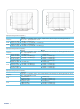
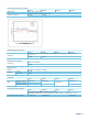
Measured frequency VS maximum input power of DSA815/DSA832/DSA875/DSA832E Measured frequency VS maximum input power of DSA815/DSA832/DSA875/DSA832E Displayed Average Noise Level (DANL ) DSA815 attenuation = 0 dB, RBW = VBW = 100 Hz, sample detector, trace average ≥ 50, tracking generator off, Frequency 20℃ to 30℃ , input impendence = 50 Ω 100 kHz to 1 MHz <-90 dBm, <-110 dBm (typ.) PA off 1 MHz to 1.5 GHz <-110 dBm + 6 × (f/1 GHz) dB, <-115 dBm (typ.) 100 kHz to 1 MHz <-110 dBm, <-130 dBm (typ.
Displayed Average Noise Level (DANL) (Normalized to 1Hz ) DSA815 DSA832 DSA875 attenuation = 0 dB, RBW = VBW = 100 Hz, sample detector, trace average ≥ 50, Frequency tracking generator off, normalized to 1Hz, 20℃ to 30℃ , input impendence = 50 Ω 9 kHz to 100 kHz <-120 dBm (typ.) <-120 dBm (typ.) <-110 dBm, 100 kHz to 1 MHz <-135 dBm, <-135 dBm, <-130 dBm (typ.) <-138 dBm (typ.) <-138 dBm (typ.) 1 MHz to 5 MHz <-130 dBm + 6 × (f/1 GHz) dB, 5 MHz to 1.5 GHz <-140 dBm, <-140 dBm, <-135 dBm (typ.
Level Display Logarithmic level axis Linear level axis Number of display points Number of traces Trace detectors Trace functions Units of level axis 1 dB to 200 dB 0 to reference level 601 3 + math trace normal, positive-peak, negative-peak, sample, RMS, voltage average quasi-peak (with EMI-DSA800 option) clear write, max hold, min hold, average, view, blank dBm,dBmV, dBμV, nV, μV, mV, V, nW, μW, mW, W Frequency Response Frequency response 100 kHz to 1.5 GHz PA off 1.5 GHz to 3.2 GHz 3.2 GHz to 7.
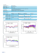
Input Attenuation Switching Uncertainty DSA815 DSA832 Setting range 0 to 30 dB, in 1 dB step fc=50 MHz, relative to 10 dB, 20 ºC to 30 ºC Switching uncertainty <0.5 dB <0.3 dB DSA875 DSA832E Measured ATT switching uncertainty VS temperature of DSA815/DSA832/DSA875/DSA832E Absolute Amplitude Uncertainty DSA815 DSA875 DSA832E DSA832 fc = 50 MHz, peak detector, preamplifier off, attenuation = 10 dB, input signal level = -10 dBm, 20 ºC to 30 ºC <0.4 dB <0.
RF Input VSWR VSWR RIGOL 11 300 kHz to 1.5 GHz 1.5 GHz to 3.2 GHz 3.2 GHz to 7.5 GHz DSA815 attenuation ≥ 10 dB <1.5 (nom.) DSA832 DSA875 DSA832E <1.5 (nom.) <1.5 (nom.) <1.5 (nom.) <1.8 (nom.
Distortion Second Harmonic Intercept Second harmonic intercept (SHI) DSA815 DSA832 DSA875 fc ≥ 50 MHz, input signal level = -20 dBm, attenuation = 10 dB +40 dBm +45 dBm DSA832E +40 dBm Third-order Intercept Third-order intercept (TOI) DSA815 DSA832 DSA875 DSA832E fc ≥50 MHz, two -20 dBm tones at input mixer spaced by 200 kHz, attenuation = 10 dB +10 dBm +11 dBm, +15 dBm (typ.
Spurious Responses Spurious response Intermediate frequency System related sidebands Input related spurious DSA815 DSA832 DSA875 DSA832E input terminated 50 Ω, attenuation = 0 dB, 20ºC to 30ºC <-88 dBm (typ.) <-90 dBm[1], <-100 dBm (typ.
Trigger Functions Trigger Trigger source External trigger level free run, video, external 5 V TTL level SSC-DSA (Option) (Only for DSA815) Signal Seamless Capture (SSC) Measurement bandwidth 1.
Input /Output Front Panel Connectors impedance RF input connector impedance Tracking generator output connector 50 Ω (nom.) N female 50 Ω (nom.) N female Internal/ External Reference frequency output level Internal reference impedance connector frequency input level External reference impedance connector 10 MHz +3 dBm to +10 dBm, +8 dBm (typ.) 50 Ω (nom.) BNC female 10 MHz ±5 ppm 0 dBm to +10 dBm 50 Ω (nom.) BNC female External Trigger Input External trigger impedance input connector 1 kΩ (nom.
Electromagnetic Compatibility and Safety in line with EMC instruction (2014/30/EU), in line with or exceed IEC61326-1: 2013/EN61326-1: 2013 Group 1 Class A standard CISPR 11/EN 55011 IEC 61000-4-2:2008/EN 61000-4-2 ±4.0 kV (contact discharge), ±8.0 kV (air discharge) 3 V/m (80 MHz to 1 GHz); 3 V/m (1.4 GHz to 2 GHz); IEC 61000-4-3:2002/EN 61000-4-3 1 V/m (2.0 GHz to 2.7 GHz) EMC IEC 61000-4-4:2004/EN 61000-4-4 1 kV power lines IEC 61000-4-5:2001/EN 61000-4-5 0.
Ordering Information Model Standard accessories Options Description spectrum analyzer, 9 kHz to 1.5 GHz spectrum analyzer, 9 kHz to 3.2 GHz spectrum analyzer, 9 kHz to 7.5 GHz spectrum analyzer, 9 kHz to 3.2 GHz spectrum analyzer, 9 kHz to 1.5 GHz (with tracking generator, factory installed) spectrum analyzer, 9 kHz to 3.2 GHz (with tracking generator, factory installed) spectrum analyzer, 9 kHz to 7.5 GHz (with tracking generator, factory installed) spectrum analyzer, 9 kHz to 3.
HEADQUARTER EUROPE NORTH AMERICA JAPAN RIGOL TECHNOLOGIES, INC. No.156,Cai He Village, Sha He Town, Chang Ping District, Beijing, 102206 P.R.China Tel:+86-10-80706688 Fax:+86-10-80720067 Electronic Measurement Instrument service and support email:EMD_support@rigol.com RIGOL TECHNOLOGIES EU GmbH Lindbergh str. 4 82178 Puchheim Germany Tel: 0049- 89/89418950 Email: info-europe@rigol.com RIGOL TECHNOLOGIES, USA INC. 8140 SW Nimbus Ave. Beaverton, OR 97008 Tel: 877-4-RIGOL-1 Email: info@rigol.